RD8 Snap Fit Calculator
Free Snap Fit Calculator - for Robust Design Snap Fits - working every time - handles variation and ensure self-locking.
Run 2.5 million dimension combos and select the one with minimum variation of your selected target in no time.
What's next?
Embed calculations like this in your project. Track and mature mechcanical interfaces and tolerance the RD8.Software application.
RD8.Software is integrated with the a CAD file, tolerance lookups, can do Monte Carlo simulations, check your constraint assumptions and much more.
Snap Fit types
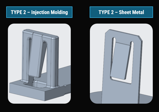
Three Robust Snap Fit types are featured in the app.
The types are guiding and should be tailored to the given application and manufacturing settings.
E.g. 'Type 2' would look different in plastic injection molding vs. sheet metal.
How to use the calculator
The calculator is intended for qualified estimates - ensuring that a snap design is ball park OK rather than 200% off target.
For more detailed calculations and analysis see RD8.Software.
Main features of the free app:
- Checks if the snap geometry is self-locking
- Checks for strain limits (ensuring that the snap will not break during assembly)
- Estimates assembly force
- Can do a quick 'goal seek' to fit dimensions to a wanted assembly force and/or safety factor.
How to use
r
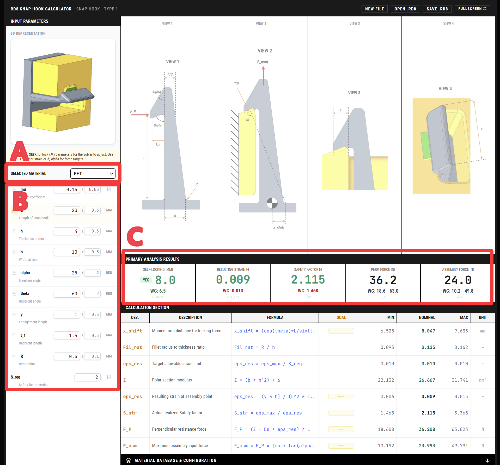
- A) Choose material
- B) Input dimensions and tolerances
- C) Review the results
- Eventually use the goal-seek function to reverse the calculations
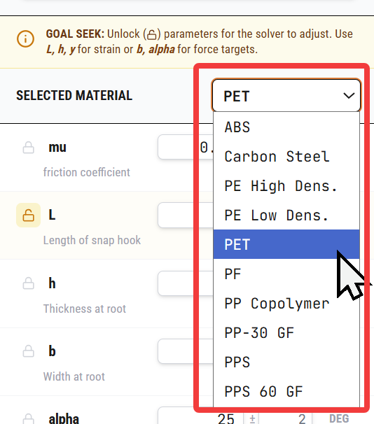
A) Choose material
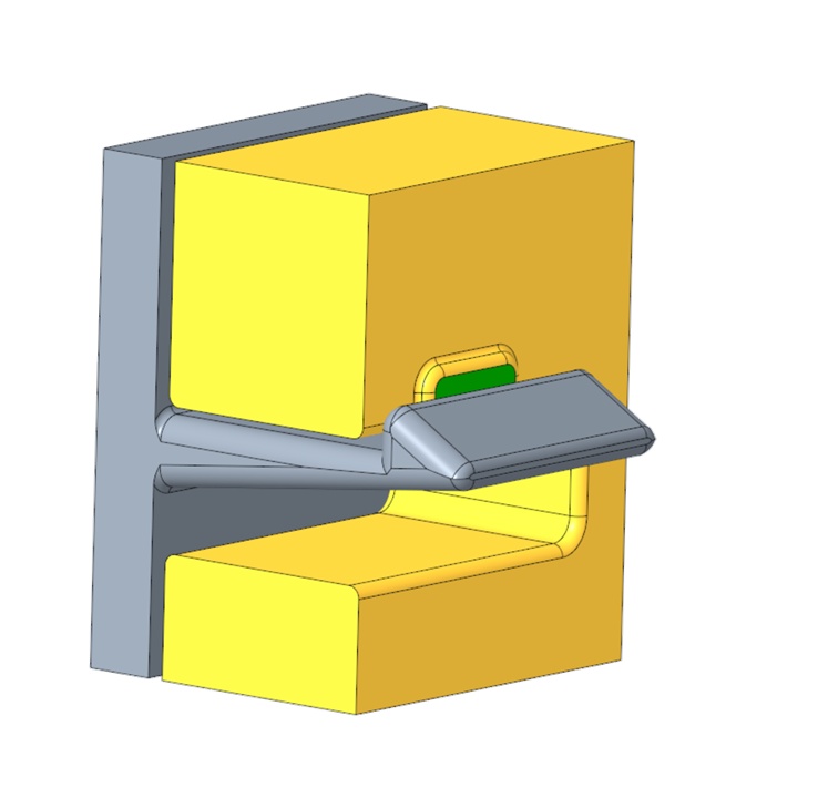
The selected material is for the snap hook (the grey part). The other part is assumed infinitely stiff.
The app features a set parameter list with RD8 values. You can unfold the list, edit and/or add new materials.
You can use the save function to save the setting/calculation.
Feel free to share you favorite materials and datapoints if you would like to have them added as defaults. Share by email to RD8.
B) Input dimensions
Click an input cell to see the matching view with illustration of the given dimension.
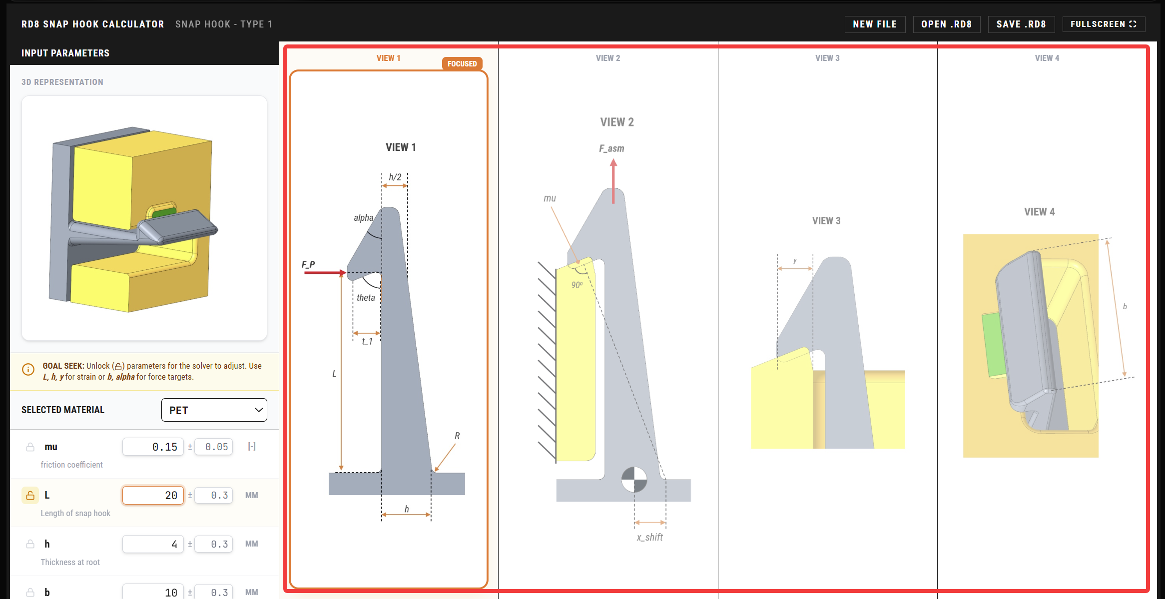
C) REVIEW THE RESULTS
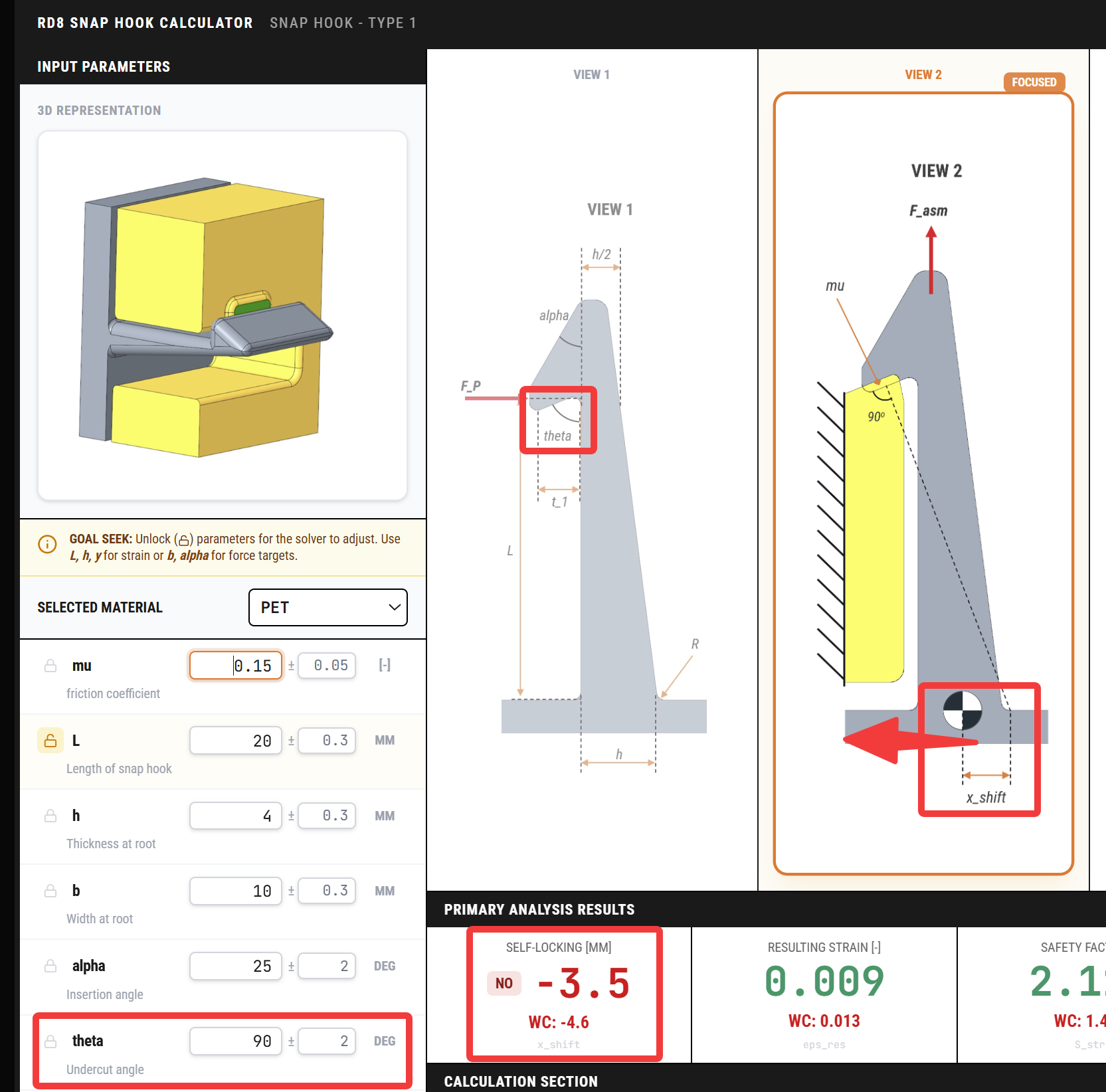
Check for self-locking
If x_shift is less than 0 mm then the system is not self locking.
If a force is acting opposite the assembly force - at some point - the snap will open up. In most cases this is undesirable.
The self-locking ability is depending on the theta angle, the length, L, thickness at root, h, and t_1.
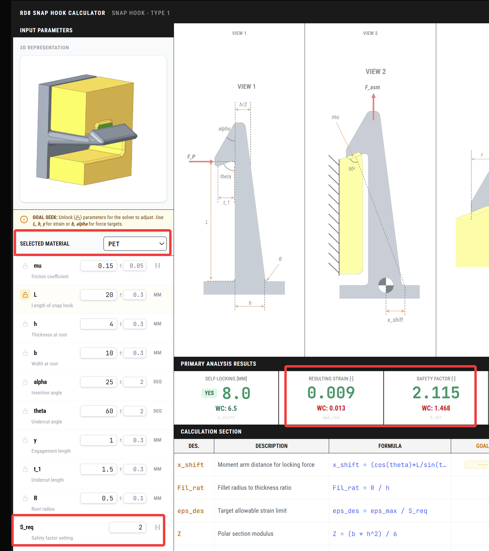
Resulting Strain and Safety Factor
When assembled - the snap hook will be displaced by the distance "y".
Depending on the material selection and the dimensioning of the snap hook - the snap hook will be exposed to a certain strain. If the strain is greater than the material properties, the snap is likely to fail.
It is often seen that the nominal value is OK - but when variation kicks-in - then in some cases the worst case scenarios are NOT OK. This calulator checks for the worst case.
The safety margin of the resulting strain is expressed as a safety factor. The wanted safety factor limit can be set in the input fields.
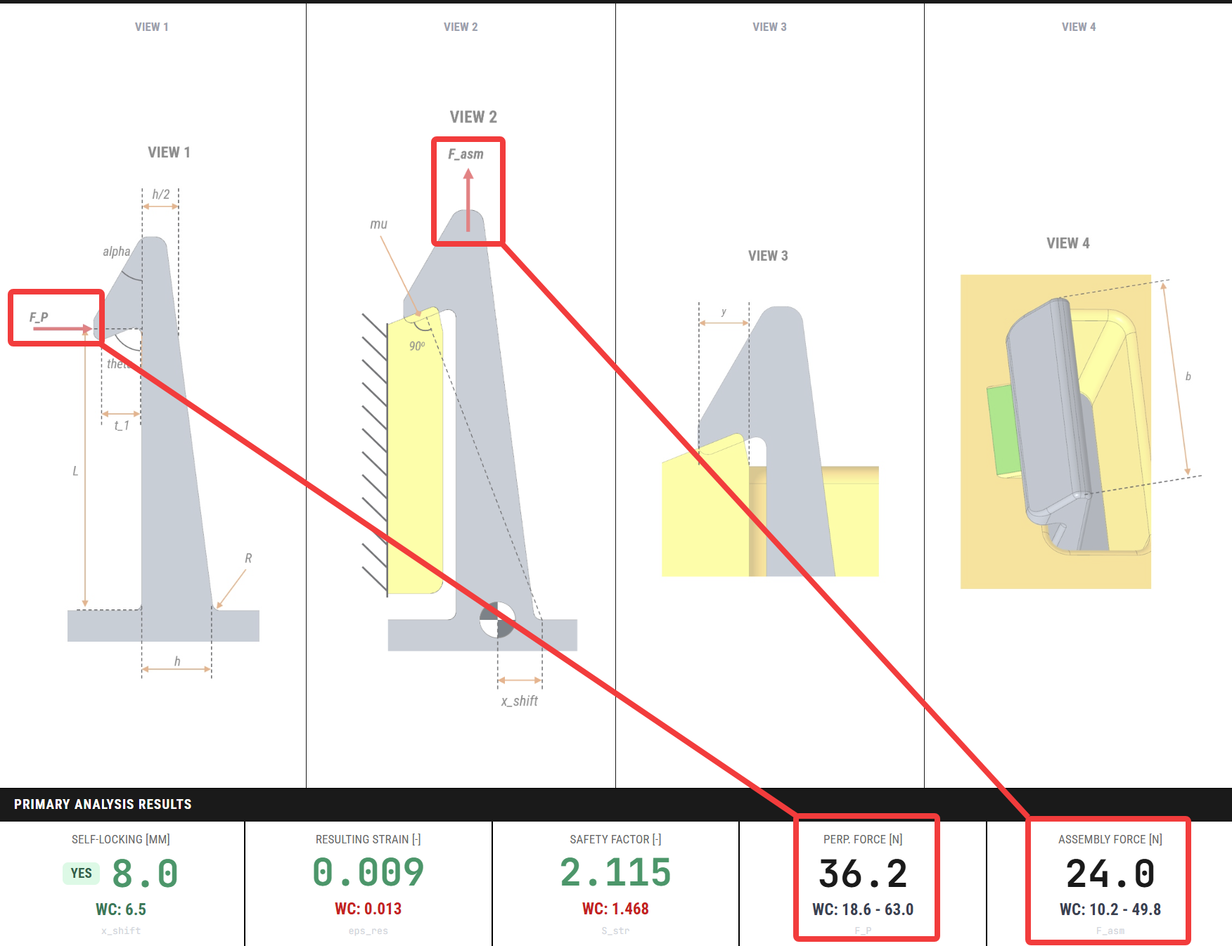
Assembly Force and Perpendicular Force
If a given assembly force is to be obtained the nominal values and expected range due to tolerance assumptions are stated.
The 'Perpendicular Force', F_P, is stated as a reference.
GOAL SEEK
The goal seek function can be used to define a set of goals and then reverse-calculate the needed dimensions.
To do this - simply:
- type in the goal(s) (nominal values)
- unlock the parameters that the app is allowed to tweak
- define the max and min limits for the unlocked parameter(s)
- define the 'bin'-size for the unlocked parameter set
(the resolution of the optimization study - e.g. a bin size of 11 with max of 50 and min of 30 creates 11 values between 30 and 50: 30, 32, 34, 36, 38, 40, 42, 44, 46, 48, 50. There is a max limit of 2,500,000 combinations - adjust the bin sizes to be within the given limit.)
- define the error margin (default is set to 5%)
- choose the optimization selection criteria with the radio buttons (the solver will choose the solution with the minimum variation in the solution space)
- click solve
The values in the input section are now tweaked to match the goals

Make quick estimates
The intention of the tool is to make qualified, realistic estimates, so that you are sure that you allocate the needed space and dimensioning to achieve the desired function.
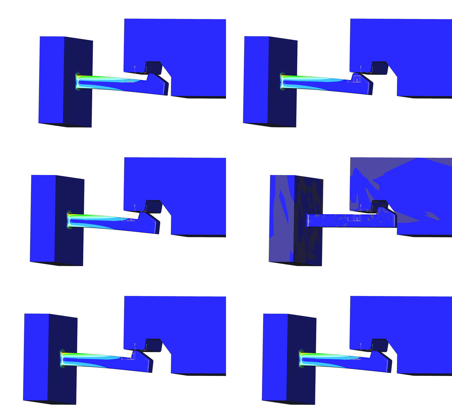
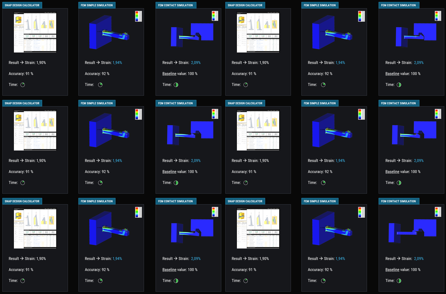
See the chart below - comparing the calculated results with a simple simulation and more sophisticated contact simulation.
The calculation is approximately 10% off the simulated value - at a fraction of the time.
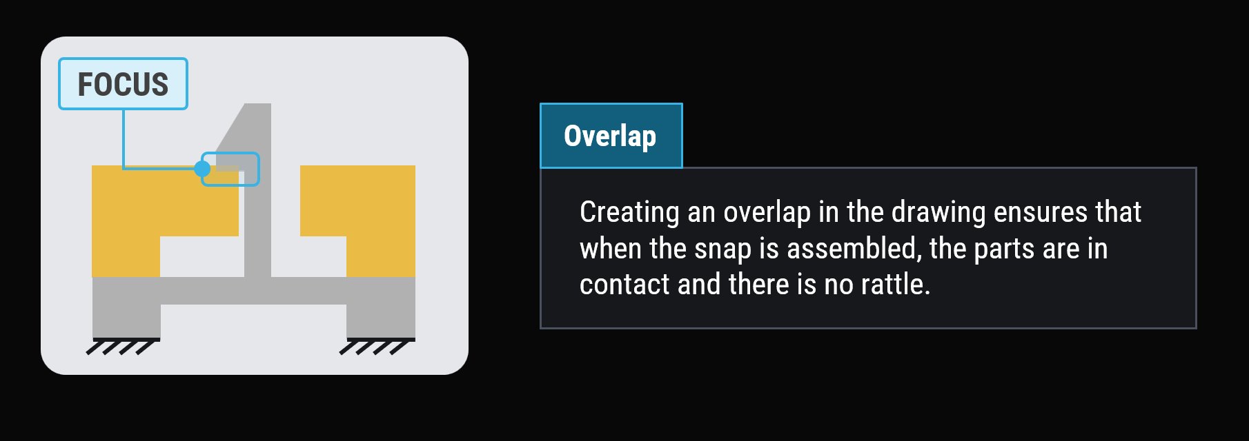
Overlap = No rattle
Ensure an overlap between the snap and the mating part - to guarantee that there will be no rattle.
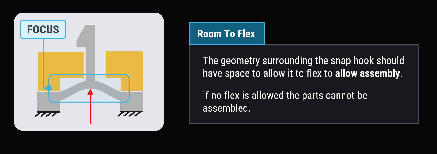
Flex for assembly
If an overlap and no rattle is desired - then there should be efforts made to ensure that the parts can be assembled. Placement of local compliant features / flexible features is needed in order to achieve this.
This can be done in various ways depending on the application, material selection and process.
The point is illustrated to the right.
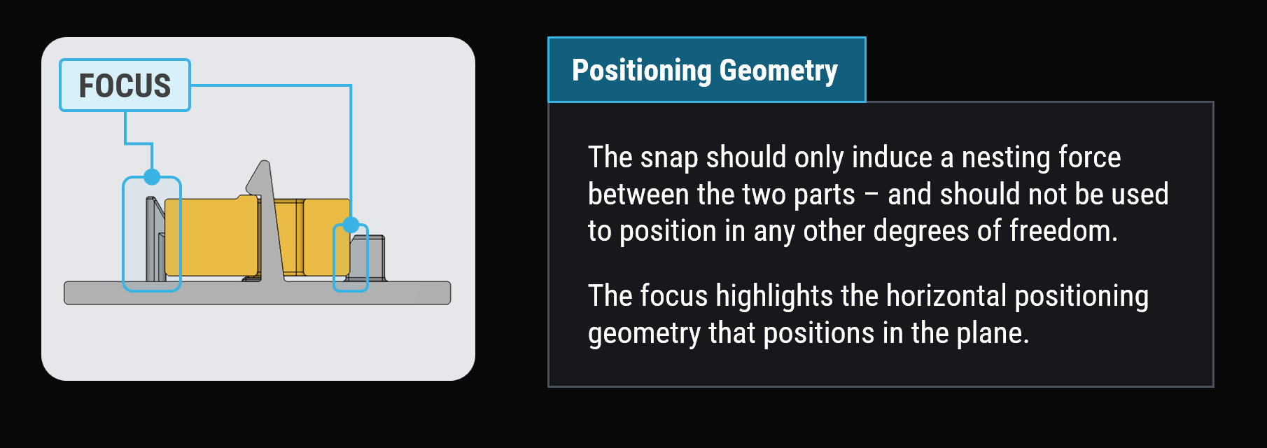
The snap should only snap
Make sure that the only function that the snap hook serves is to 'snap' and create a nesting force.
It is often seen that the core geometry of snap is used for part positioning. This is not recommended.
It is recommended to keep positioning and snap features as distant features as shown on the illustrations - where other features serve the purpose of positioning in the plane.
Self-locking snap Fits
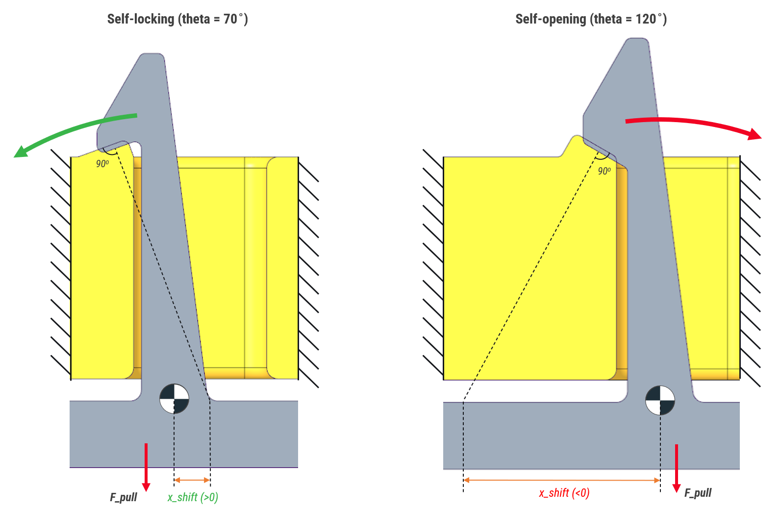
The geometry of the snap fit define if the snap fit hook is self locking or not.
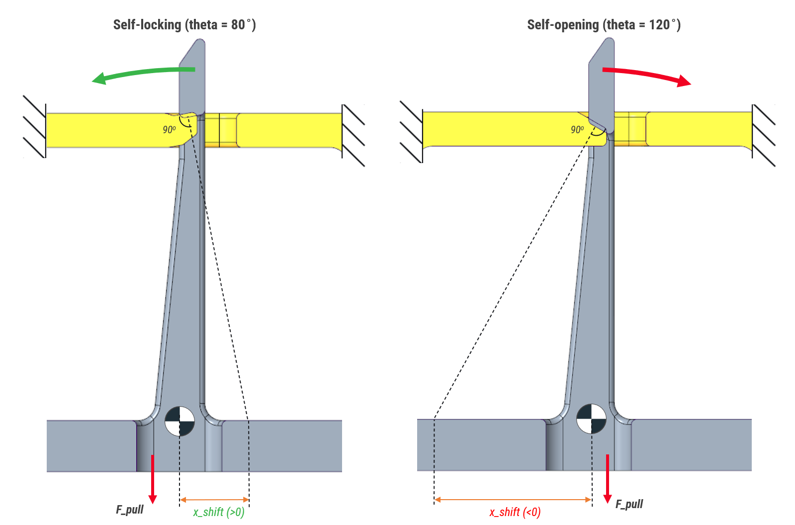
A projected line from the snap hook surface relative to the virtual hinge point determines if the snap hook will be self-locking or not.
This is illustrated with two theta angles; 70 deg., and 120 deg.
The example with the 70 deg., theta angle.
If a force, F_pull, is pulling in the snap hook, the pulling force will reinforce the snap to engage even more, hence self locking.
In the other case where the theta angle is 120 deg., if a pulling force is acting in the direction shown, the snap will deflect away from the engament surface and disengage. Hence it will be NOT self locking, it will be 'self-opening'.
Self-opening snap fits can be benificial for fits where disassembly by force is inteded.
Otherwise self-locking snap fits are recommended to ensure a fit - always.
The same goes for the 'Type 3' snap hook.
Self-Locking Snap Fits: Explainer Video
The self-locking principle is explained in the video below.
Try The other Napkin tools
Contact and Clearance Calculator

Spring Calculator
Guide Ratio Calculator

Ensure that energy is not lost to friction and that your design is operating with maximum efficiency.
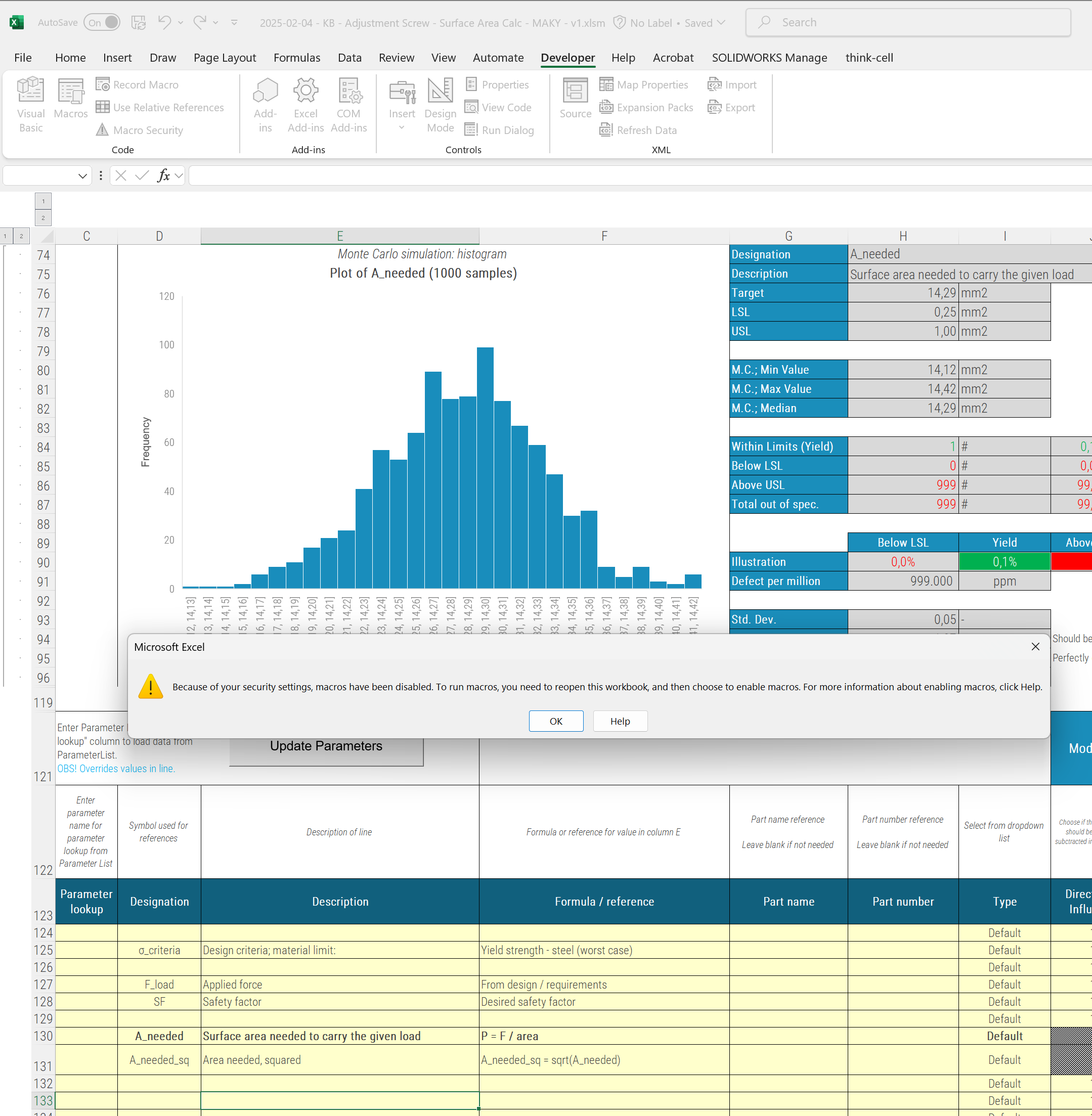
Can You Do Tolerance Stack-Up Analysis in Excel?
Yes, tolerance stack-up analysis can be performed in Excel. Thus Excel has it's limitations.
Excel is commonly used for simple or basic stack-up calculations, especially for linear dimension stacks and worst-case calculations.
Each country seems to have their 'excel template' that has been circulated and improved, tweaked, altered by each company.
Some excel templates can do RSS, some has a built in parameter list, some has more advanced macros.
When macros are present - you cannot work simultaneously in the sheets. You can in RD8.
When worst case and RSS is not enough - you can work with statisical and Monte Carlo simulations in RD8.
Typically you cannot apply assymetric tolerance in Excel - you can in RD8.
Filehistory is typically based on One-Drive - often random - in RD8 you work with iterations and user logs.
Excel is prone to errors - if you delete a row or delete a formula in the wrong cell - hell is loose - not in RD8.
Excel gives a lot of freedom to different style for annotation, tolerance setting and assumptions - in RD8 everything is uniform and streamlined.
In Excel you manually have to lookup suiting tolerances - in RD8 suiting tolerances can be looked up automatically.
In Excel - the workflow is scattered between different applications. CAD for screenshots. Power Point or Paint for making annotaions. Excel for the calculus. In RD8 everything is in one application.
And the list goes on...
Set up a free RD8 Software Trial for your team
Book an initial meeting to:
Let us know your contact details - and any additional clarification points - then we will get back as soon as possible.
By submitting, you accept RD8's Privacy Policy and Terms of Service.
