"Tested" by Adam Savage: An in-depth review of the world's best keyboard.
Watch the video review now

Critical-to-Quality: from user need to inspection dimension

Getting the link right from user need, all the way down to the critical dimension/tolerance on the drawing to be able to guarentee quality.

The journey is long.

Black right-pointing chevron arrow inside a white circle.
From user need to a functional specification
Black right-pointing chevron arrow inside a white circle.
From functional specification to an idea.
Black right-pointing chevron arrow inside a white circle.
From idea to feasibility studies (calculations, initial stack-ups, principles, ...)
Black right-pointing chevron arrow inside a white circle.
From idea to 3D CAD concept
Black right-pointing chevron arrow inside a white circle.
From 3D CAD concept to tolerance analysis (or functional calculation)
Black right-pointing chevron arrow inside a white circle.
From tolerance analysis to 2D drawings (and inspection dimensions)
Black right-pointing chevron arrow inside a white circle.
From 2D drawings to IPC (In Process Control) / QA w. control charts
Flowchart showing product development stages: Product Specification translates User Needs to Functional Requirements; 3D CAD Model and 2D Technical Drawings are created; Tolerance Analysis is calculated; resulting in In Process Control tracking with control charts.

Home

/

Industrial Products

/

Critical-to-Quality

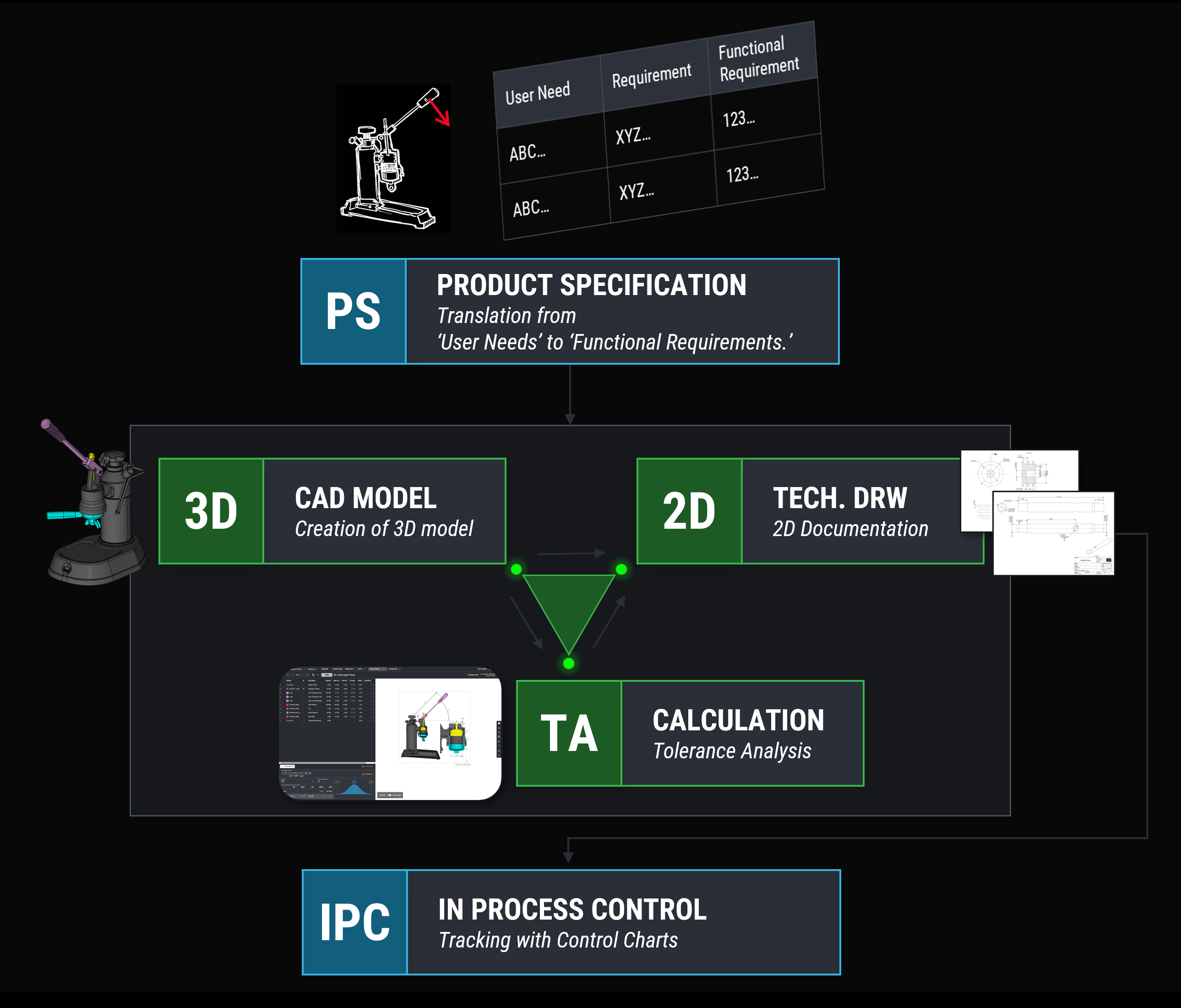
Breakdown of User Needs to Clear Functional Requirements

R&D units struggle with the missing link of being able to predict the quality based on the design documentation.

Not only prediction of quality - but also the capability of being able to monitor and check the critical dimensions to keep quality in control is a missing part in most mechanical departments.

It all starts with a clear breakdown of requirements.

The breakdown of user needs to requirements and functional requirement is in poor condition or not clear at all. 
Systematic breakdown of the product specification:

User Needs --> Requirements --> Functional Requirements (a functional specification that can be stated in physical units). 

Alignment between product owners, project managers, chief engineers, mechanical engineers,...
Table listing user needs, requirements, and functional requirements for nostalgic brewing, alongside a white outline drawing of a mechanical press with a red arrow pointing to the handle.
Screenshot showing tolerance analysis of gasket overlap in RD8 software with corresponding 2D technical drawings linked by colored lines.

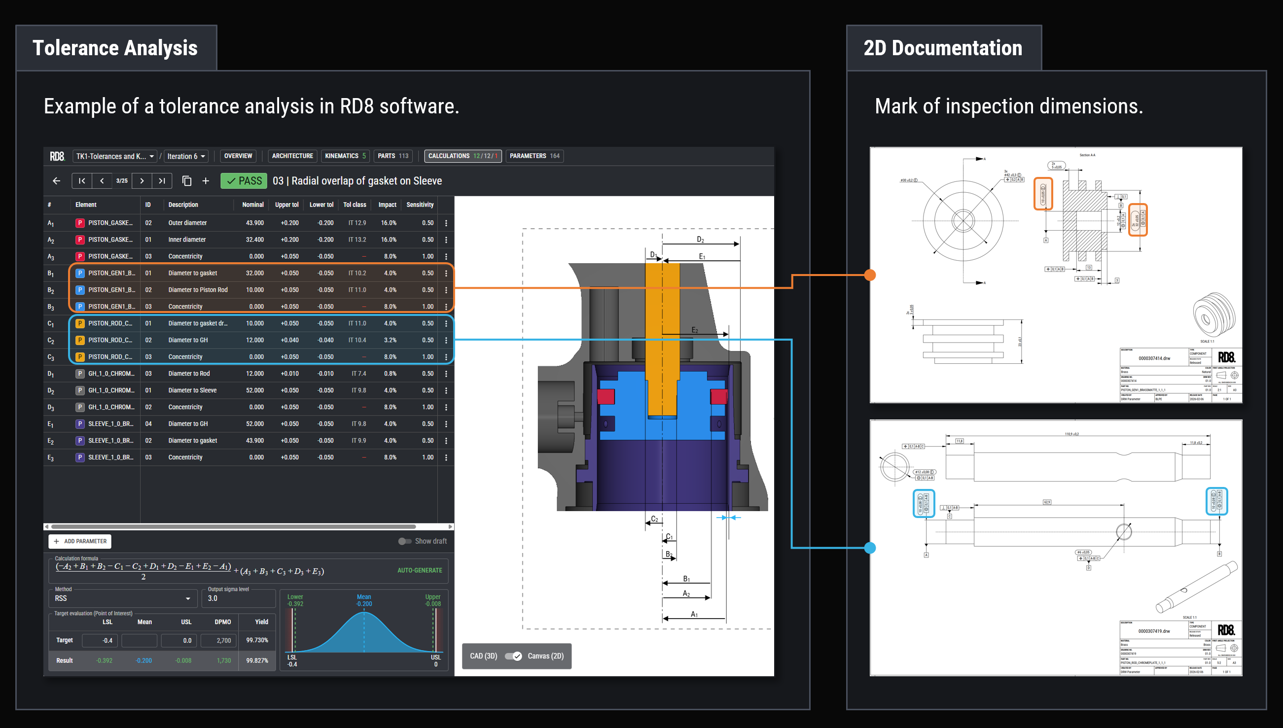
Trace the dimensions critical to quality

Most drawings are full of dimensions, tolerances, notes - but which are the critical ones?

Drawings are over specified or unclear. Critical dimensions are not marked as inspection dimensions.
Use the RD8 Software to calculate and verify tolerance stacks. Use the stated values from the tolerance analysis for the 2D documentation.

Too complex to determine the critical dimensions

R&D units struggle with the missing link of being able to predict the quality based on the design documentation.
Not only prediction of quality - but also the capability of being able to monitor and check the critical dimensions to keep quality in control is a missing part in most mechanical departments.


Designs are too complex. It is impossible to specify the exact critical dimensions that are critical to quality (because all dimensions are actually important in the current drawings). See the 5-bar mechanism example here. Due to an overconstrained design - almost all dimensions are critical to quality. Any slight variation impact the function.

First.

Using Robust Design principles and RD8 Software to eliminate overconstraints enables predictability and design clarity. Know the minimum amount of dimensions needed to satisfy a function is determined.

Second.
RD8 Software
maps out the critical dimensions in functional calculations and tolerance stack-ups.
The parameter list feature highlights important dimensions for each part so they can be easily transferred to the 2D drawings.
Part dimensions can be filtered and checked in the system to ensure correct annotation on the adjacent 2D drawing for the given part.
Software interface showing calculation results with a 3D model of an automotive air vent on the right side.

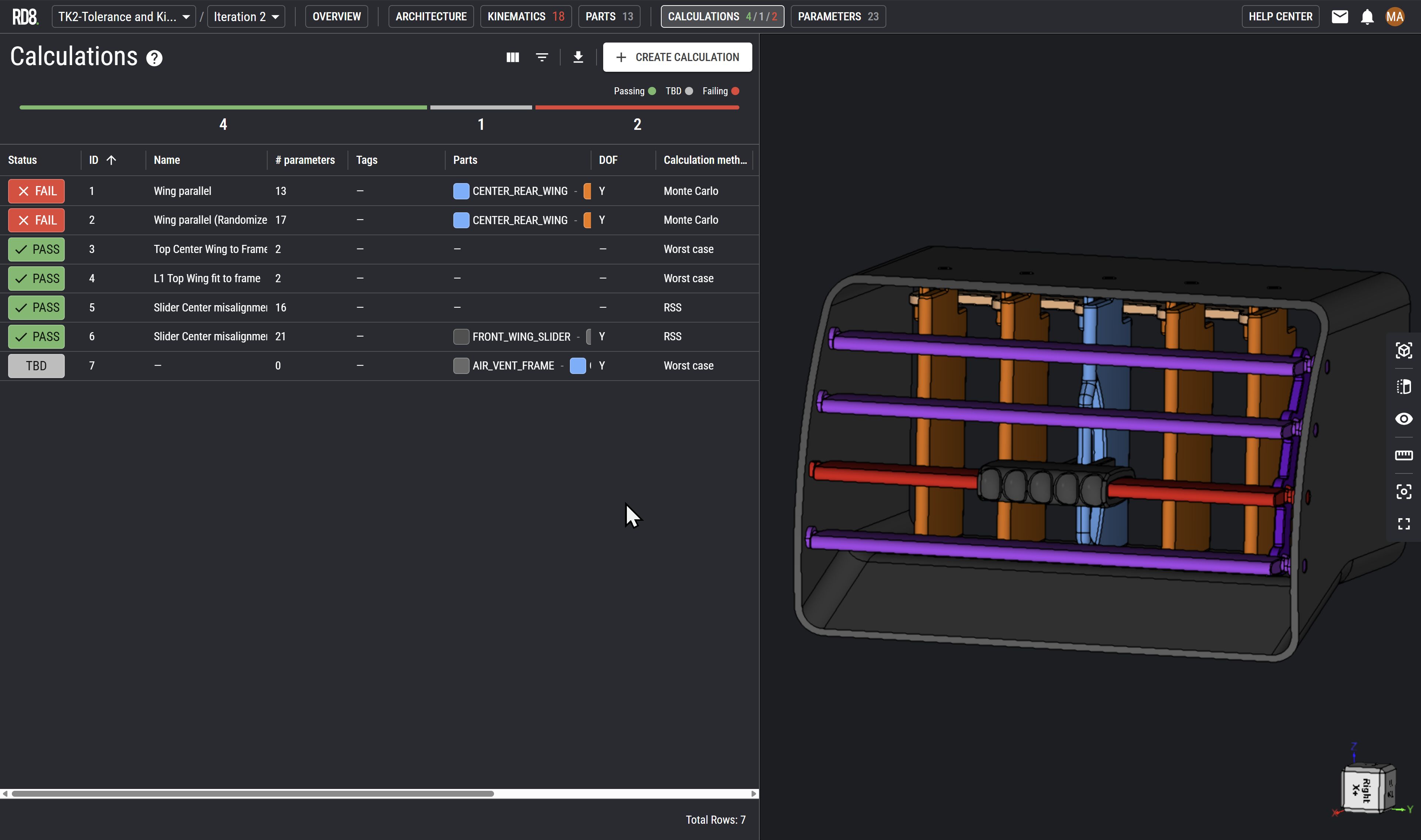
Calculations Does Not Match Reality

Often, simulations and calculations does not align with tests. Why? This frustration often leads to a culture where mechanical engineers don't calculate - but just seek out to test and experiment. In some cases an effective mean - in some it can be a very deceiving mean - as a working prototype being seen as a grant for production readiness.

Production or tests are behaving radically different from simulations and calculations and it is impossible to fix a given issue due to lost control of the product behavior.
RD8 software checks the quality of the geometrical inputs.
If a tolerance stack is ambiguous or not. In order to achieve a 1:1 correlations between simulation and output the tolerance stack should be based on crystal clear tolerance paths - and hence not be ambigious.

Get in touch with our experts

Want to know more about:

How to achieve predictability in your design - from idea to production line
Face global competition in mechanical engineering
Get the mechanical foundation right when developing innovative solutions

Shoot us a message and we will get back as soon as possible.

By submitting, you accept RD8's Privacy Policy and Terms of Service.