All the Features you need, built for Tolerance Stack-Up Analysis and Optimisation
The RD8 Tolerance Stack-Up and Optimization Software helps you to do tolerance stack-up analysis on the fly during the product development process.

Trusted by engineering teams building high‑performance mechanical products


Feature list
Assisted Setup
Analyse and Optimise
Complexity Made Easy
Preview Parameter Changes
Assisted Setup
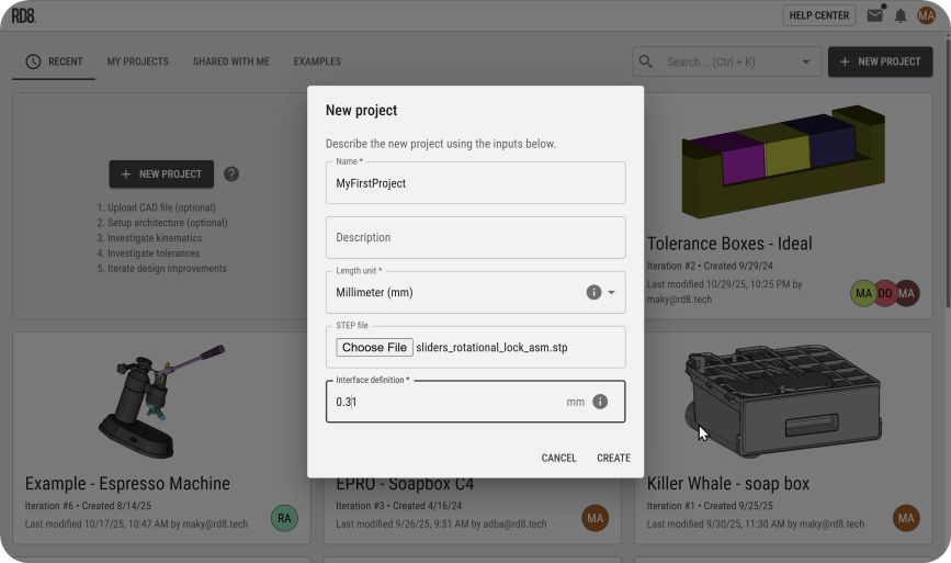
Quick Setup: STEP Import
To get started - import a ".STEP" file.
The system recognises all meta data from your .STEP file; dimensions, tolerances, GD&T annotations, part names, part colors, sub-assemblies, ...
Automatic Stack-Up Detection
Get instant help to set-up tricky tolerance stacks and check if tolerance stacks are ambigious (to avoid overconstraints).
Define a 'Point of Interest' and let the system identify possible tolerance paths. See the video to see an example.
Sketch Canvas
Draft tolerance stacks and allocate estimated tolerances based on sketches or illustrations.
Annotate on sketches to draft and communicate design intents.
Keep the design history. After sketching - link the parameters to the CAD model.
3D CAD-Viewer and 2D Infinity Canvas
Take screenshots from the embedded 3D viewer directly into the 2D Documentation Canvas. No app-switching.
Easy annotation of stacks by:
- Point of Interest annotation
- Leader lines
- Arrows
Semi automatic link of annotation to parameters and parts.
The canvas is an "infinity canvas" and can be used to add notes, screenshots, stickers to support the development and thought process.
Time Machine: Iteration Feature
Keep your work up-to-date anytime.
The "iteration feature" allows you to import a new .STEP file and keep track of design history.
The system then automatic recognises parts and changes in the design. The user will only need to approve/adjust changes where the model looks different from the previous iteration - making it easy to reuse and refine the design during the development process.
See the example in the YouTube video.
Analyse and Optimise
The built-in optimisation checker will show if there are any overconstraints in the design.
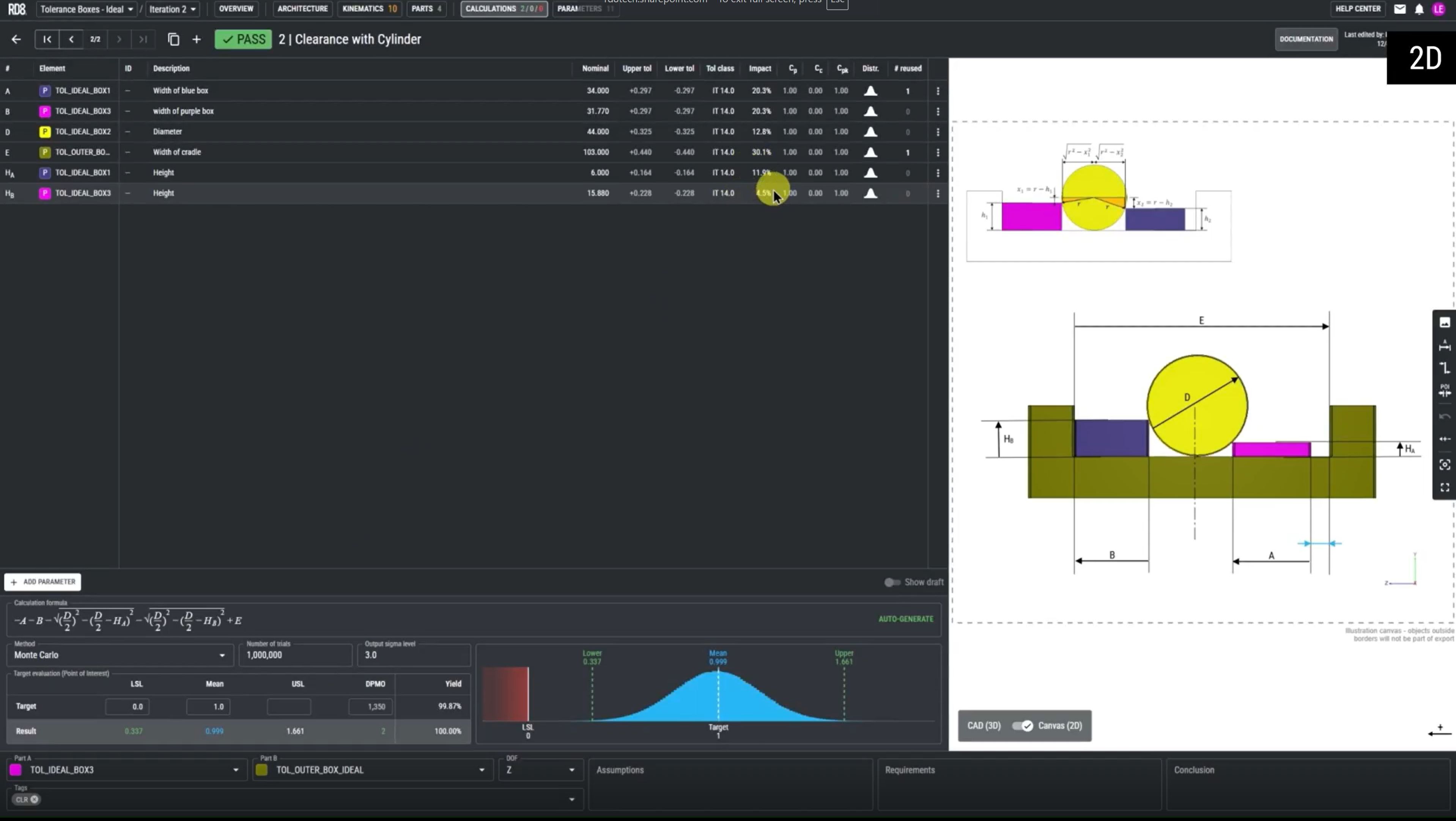
Supports Tolerance Stacks in 1D, 2D and 3D
You can also analyse 2D and 3D stacks.
The system allows you to setup multi-dimensional stacks. In combination with the iteration feature the analysis can be refined during the development process.
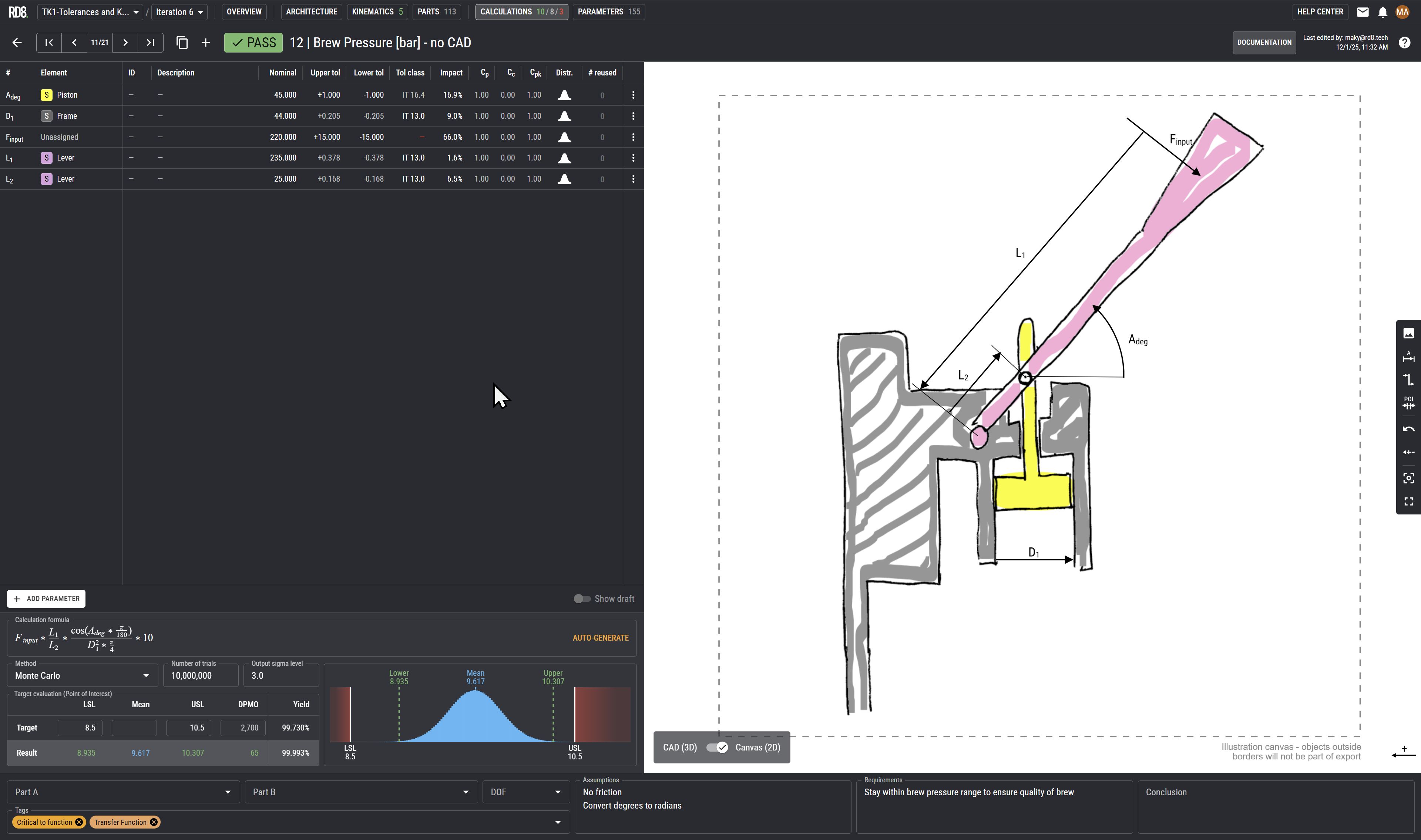
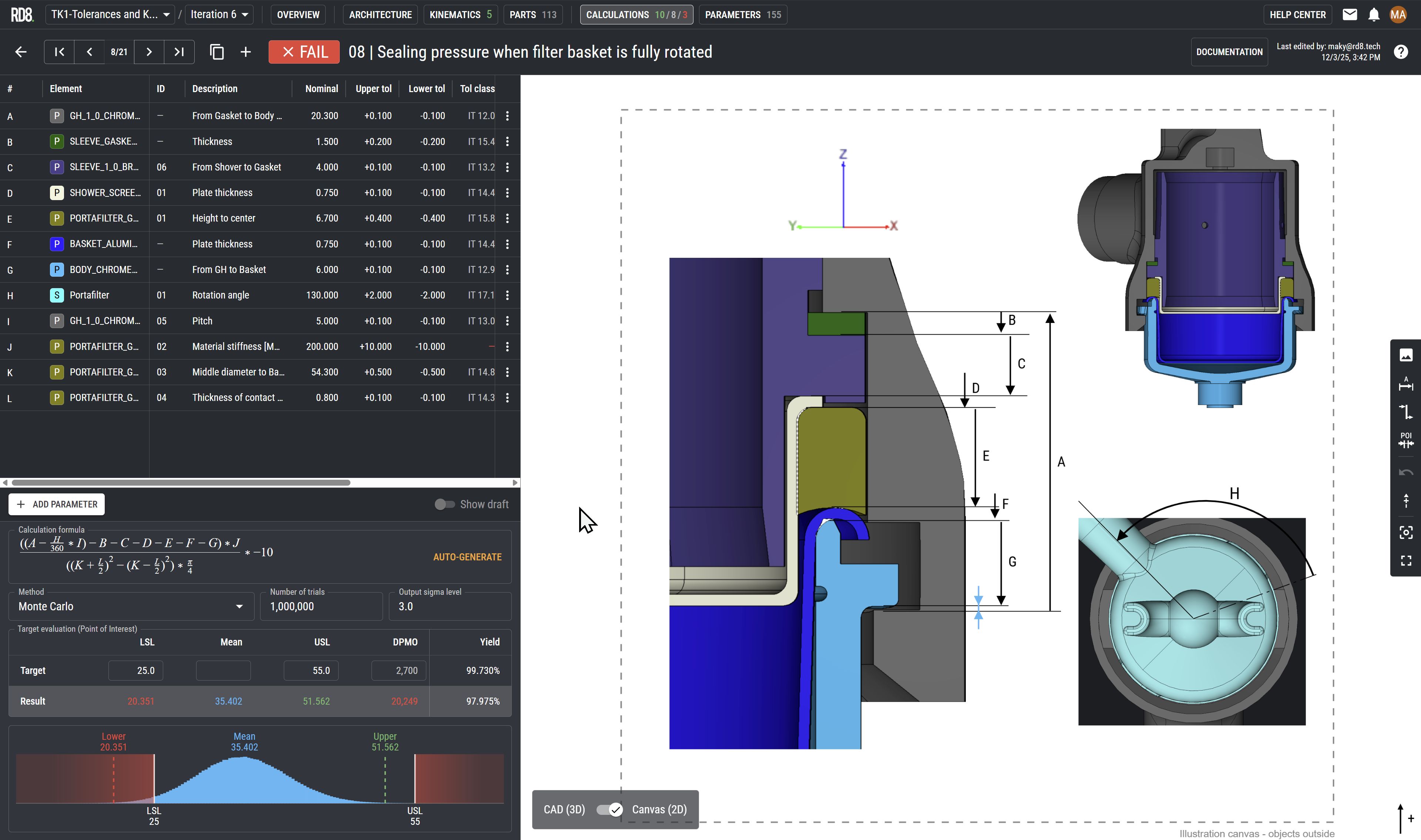
Supports Non-Linear Tolerance Stacks
Set-up non-linear stacks. Calculate forces, pressure, your commute-time-to-work, only your imagination sets the limit - as long as you can provide a mathematical expression.
The system works with all standard math-operators such as cos, sin, cosh, sinh, Pi, etc.
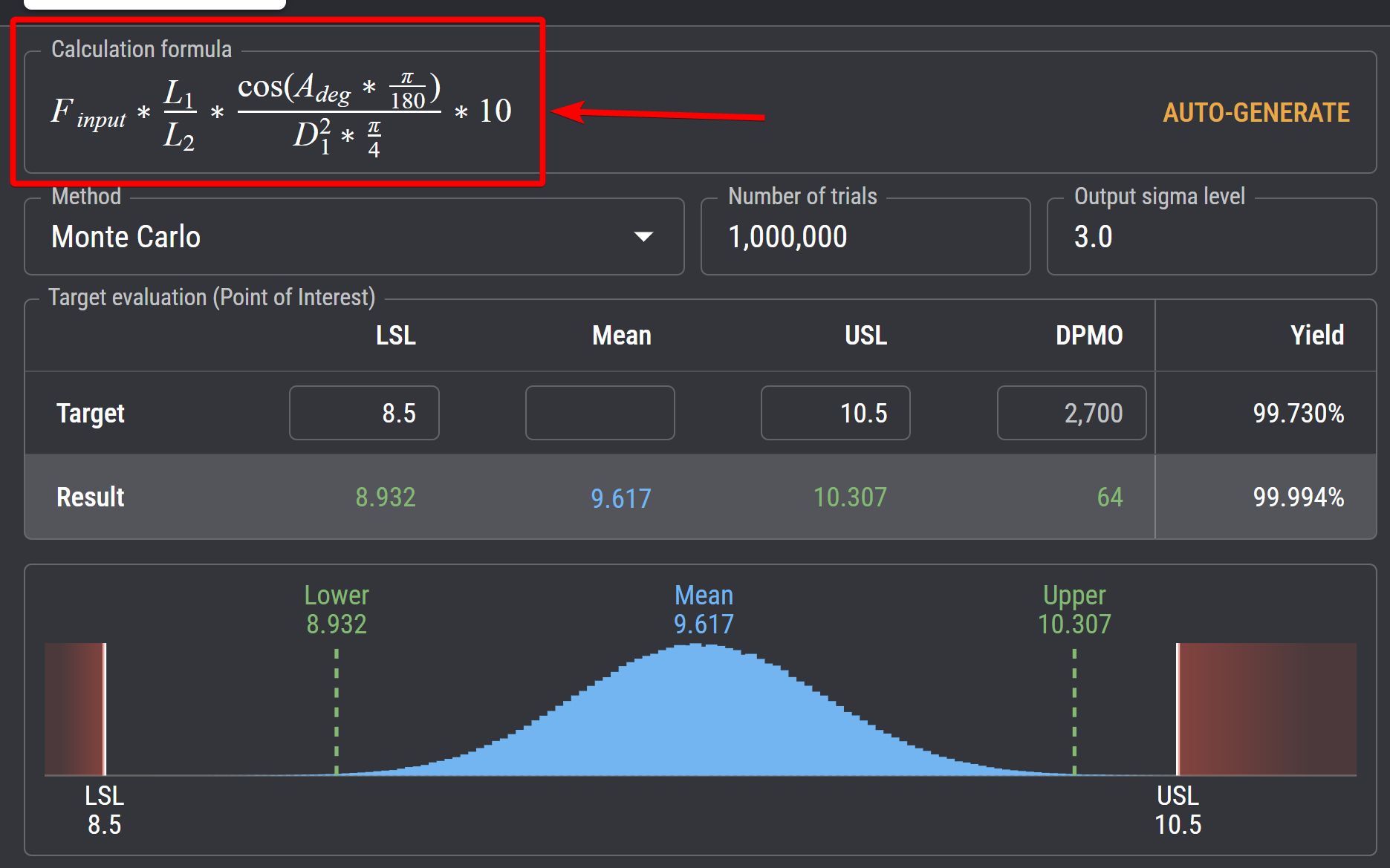
Simulating Success or Failure
Easy switch between different evaluation methods:
Also set the functional requirements:
Target, LSL (Lower Specification Limit), USL (Upper Specification Limit), Sigma Level.
Read projected DPMO and yield in a simple interface.
Tolerance Lookup
Tolerances are a part of the calulation table, so here you have a good overview of your tolerances.
The system allows you to look-up and assign tolerance on the fly based on the ISO 286 IT grade standard.
The user can either input a tolerance and then calculate the corresponding IT Grade or input a tolerance grade and then calculate the related tolerance.
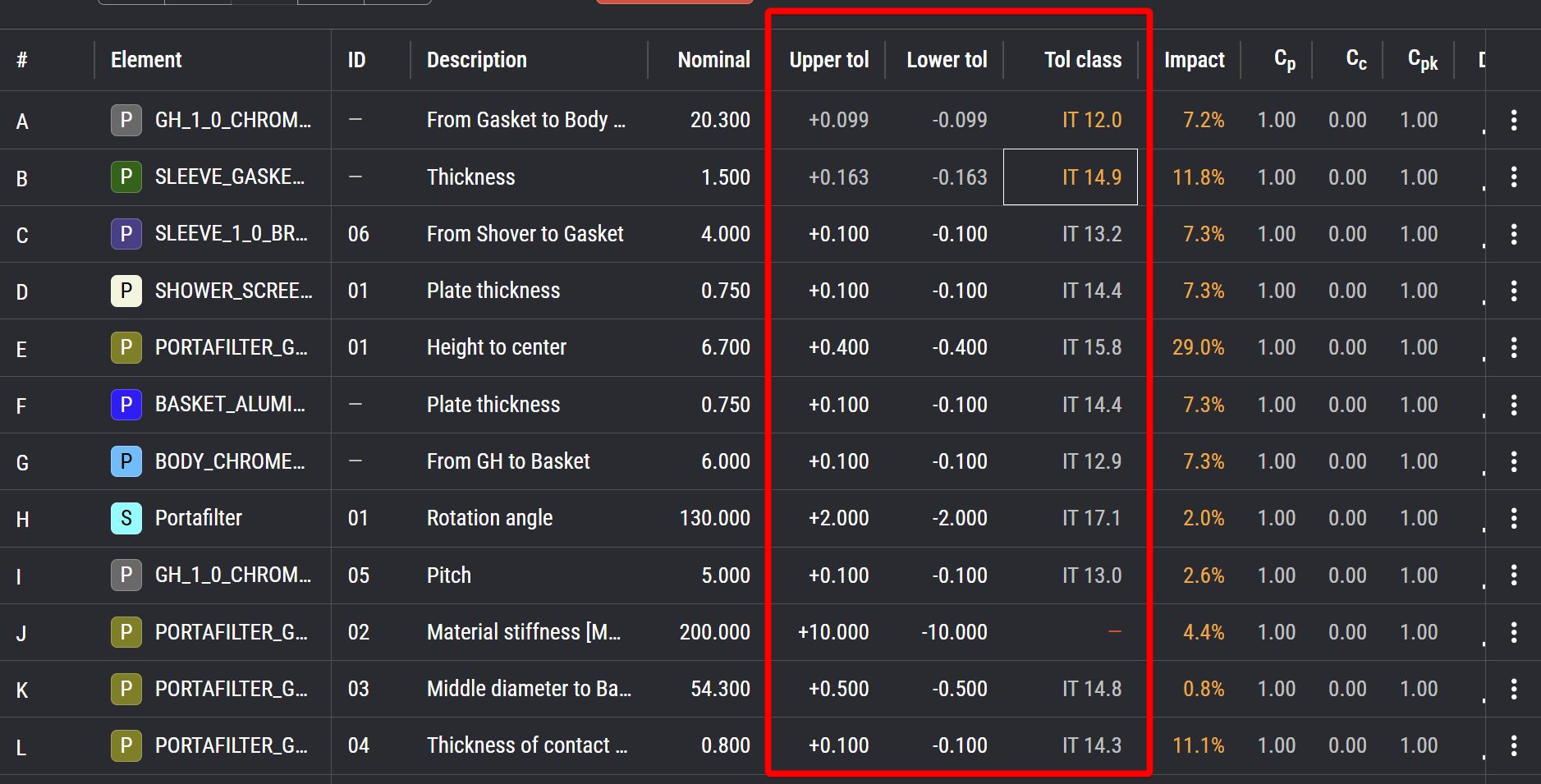
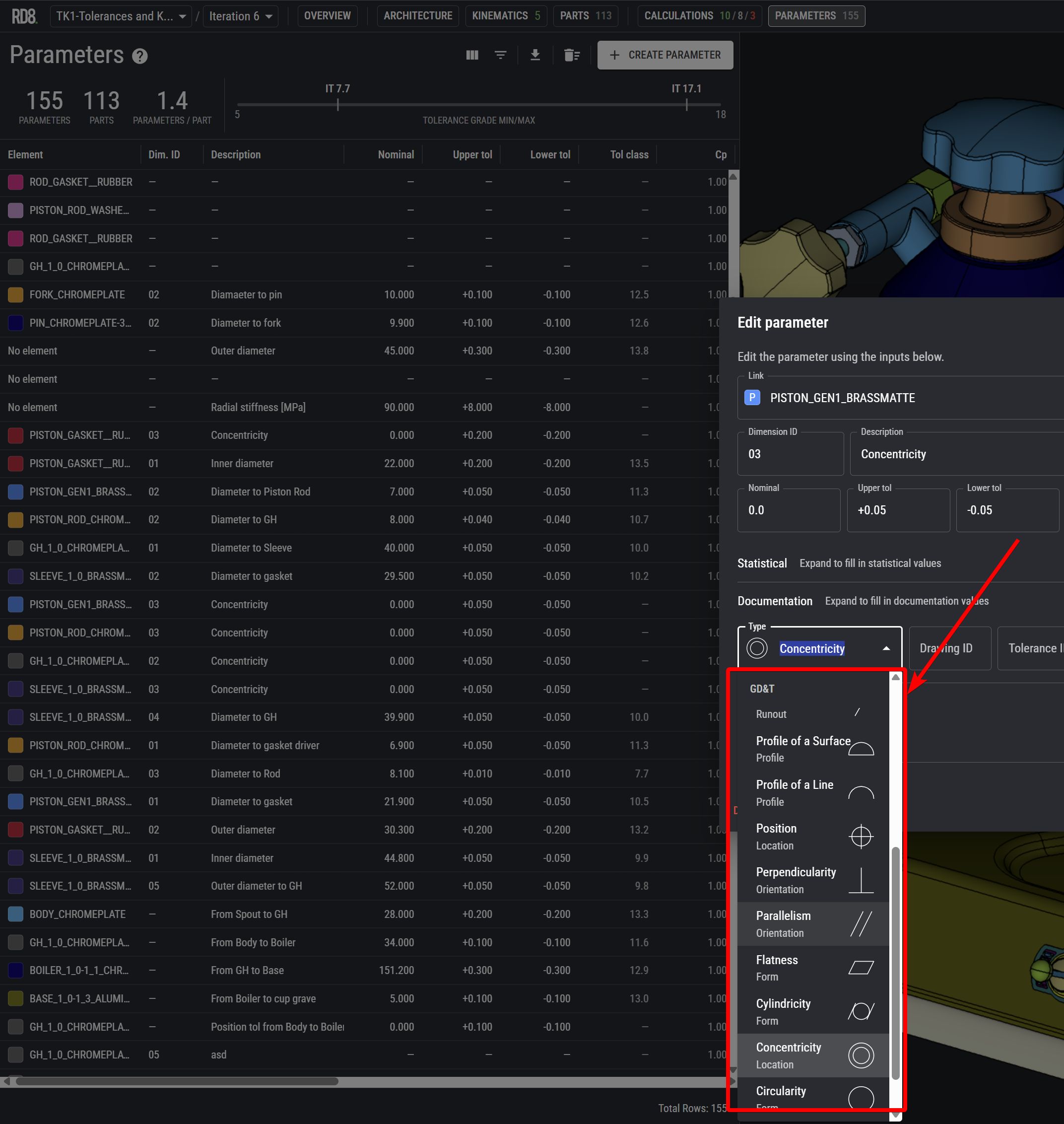
Apply GD&T Modifiers
Refine tolerance stacks with GD&T modifiers such as Symmetry, Straightness, Total Runout, Circular Runout, Profile of a Surface, Profile of a Line, Position, Perpendicularity, Parallelism, Flatness, Cylindricity, Concentricity, Circularity, or Angularity.
X-ray Interfaces and Identify Overconstraints
Our technology is built on world-leading interface engine.
Here you see an illustration of two parts - a grey and a purple.
Our 'X-ray' mode lets you inspect functional surfaces between the parts.
In this case almost all functional surfaces are highlighted in orange - indicating overconstraints. This results in unnecessary complexity for tolerancing.
Optimisation Checker
Contrary to the other example with an overconstrained design - here's an example with no overconstraints.
The 'X-ray' and constraint evaluation engine determine that there are no overconstraints and that the part is ideally constrained - indicated by green functional surfaces. The parts are exact constrained and hereby easy to tolerance.
Complexity made easy
Tolerance Stack-up Overview
Linked Calculations Sheets
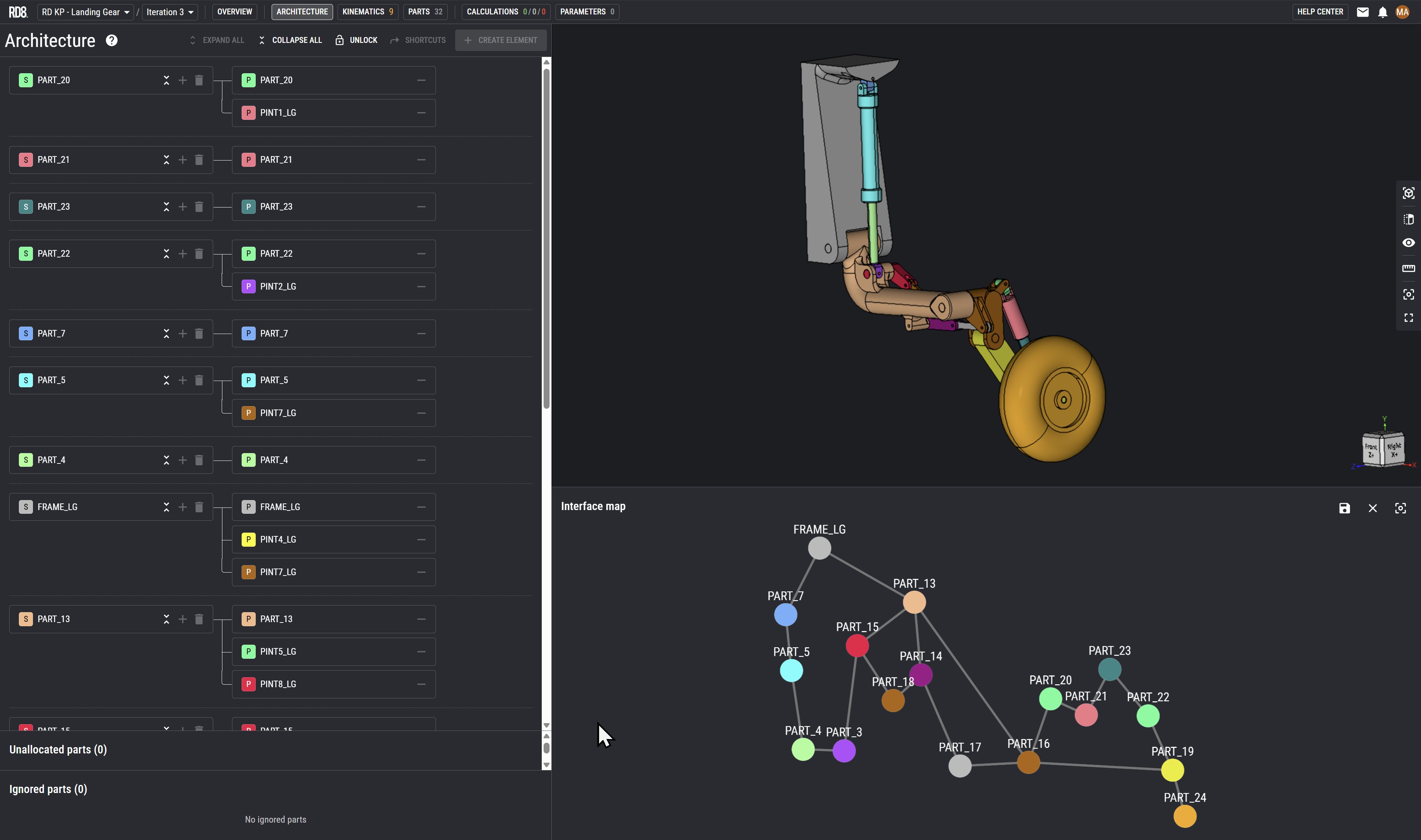
Intuitive Interface Map
Setup a product architecture from scratch or inherit the architecture from the .STEP file.
From an initial import-setting "interface definition" - the system identifies all interfaces between parts.
The architecture feature let's the user(s) arrange and re-arrange parts in assemblies and sub-assemblies to make tolerance analysis easy and simple.
The interface map feature aids the users by a graphical overview of the product architecture.
The system automatically generates the map. A mapping of part or sub-assemblies and their interfaces.
This feature is helpful to:
- layout product architecture
- divide work-tasks or areas of responsibility
- spot complexity (if the map looks like spaghetti you are most likely overcomplicating things and makes it impossible to make any valid tolerance analysis)
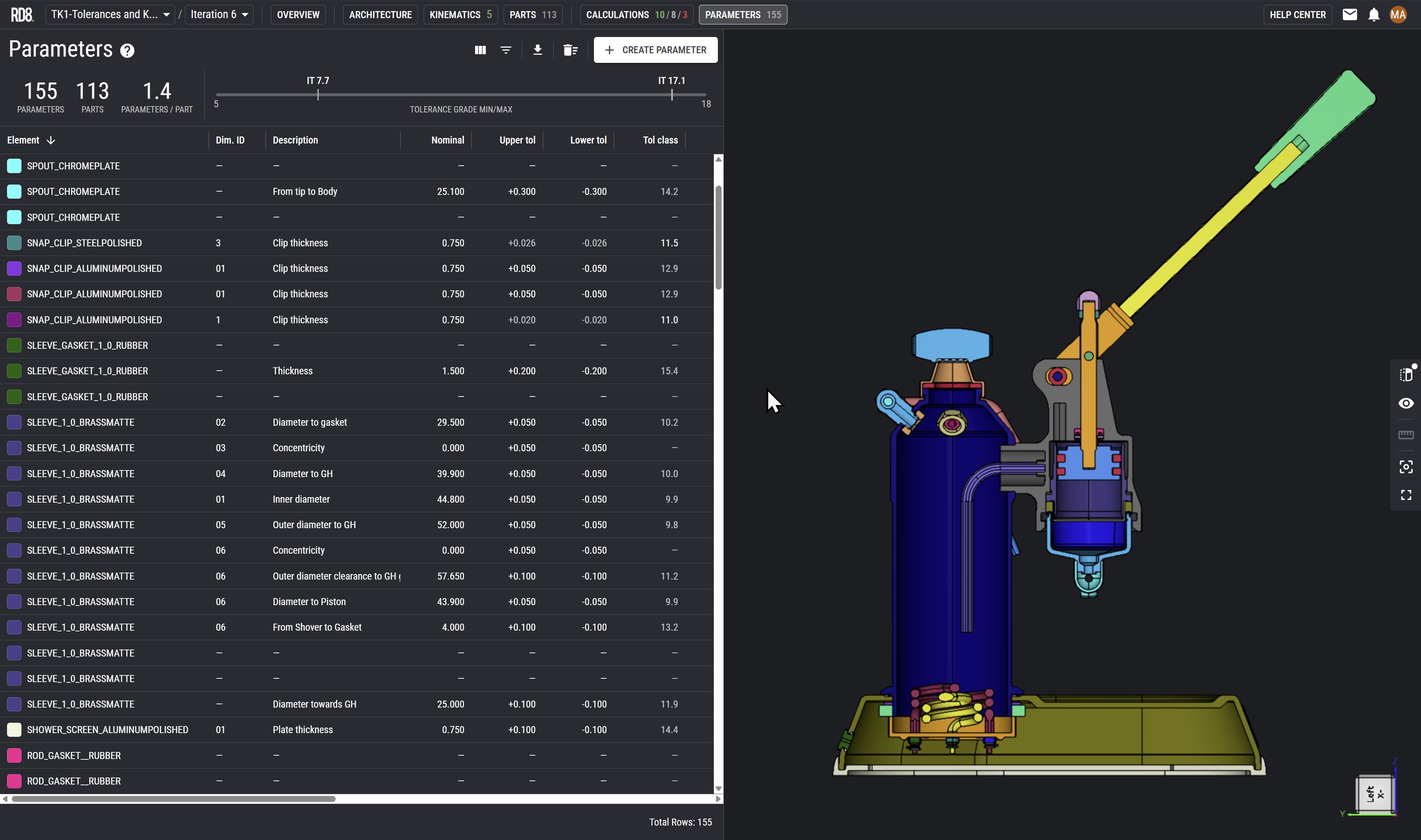
Parameter List: The Foundation for the 2D Drawing
The systems parameter module makes it easy to filter out all relevant elements that should be transferred to the final 2D drawing.
The parameter module summarises parameters from all tolerance stacks into a single list.
With respect to axiomatic design - the parameter list also reveals information regarding how many times/places an element is used which can be an indicator for how many couplings that exist in a design.
The "What if" feature.
Preview Impact of Parameter Changes
Easily preview the impact of publishing your parameter changes
"What if" this parameter changes? Instantly check the impact on other calculations.
E.g. handy in case if a part is out of specification. Check the impact in seconds.
Live Collaboration
Collaborate real-time with colleagues 'google docs style'.
Cloud based system: no check-in or check-out.
Manage and control access/viewer rights.
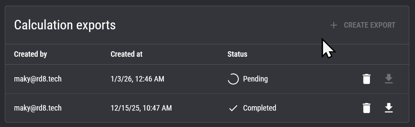
PDF Export
Export a PDF-report by a single click.
Trace design history, document, and share.
How-to create a Tolerance Stack-up Calculation in 2 min.
Easy Setup in minutes
Automatic stack-up detection
Get instant help to setup tricky tolerance stack-ups and check if chains are unambigious.
2D Canvas and Annotation
Want a Demo?
We'll contact you.
By submitting, you accept RD8's Privacy Policy and Terms of Service.
Two ways to unlock value with RD8 Software
RD8 supports both traditional expert-driven workflows and modern, scalable team workflows. Choose the approach that fits your organization today - and evolve as your engineering process matures.
Centralized Expert Workflow
For the 1-3 specialists who handle tolerance stacks today.


Scaled Team Workflow
For organizations ready to democratize tolerance stack analysis.
Set up a free RD8 Software Trial for your team
Book an initial meeting to:
Let us know your contact details - and any additional clarification points - then we will get back as soon as possible.
By submitting, you accept RD8's Privacy Policy and Terms of Service.