“It has to look perfect” and “it has to work every time” sound great on their own, but the trouble starts when they’re tied together in the same tolerance stack.
Once that happens, you usually end up fighting two battles and end up with a bad compromise no one is happy with.
Some designs treat the visual alignment and the functional alignment as the same requirement. A nice even gap on the outside (ex. panel gaps on car doors) is supposed to be perfectly parallel, and just behind the panel sits a component that must seal, snap in place, or carry loads. And now all gets thrown into one long chain of dimensions on the drawing.
In reality that means that we are trying to control multiple functions with the same interfaces and the same dimensions and tolerances. We call this a coupled system. And with coupled system there is always a compromise in terms of inputs and outputs. To solve this, tolerances need to be tighter, leading to increased tooling cost.
Sometimes, to make the situation worse, half-way into your design process, the requirements are adjusted, making your compromise impossible. Then you get to start over and find a new solution, resulting in a project delay and budget increase.
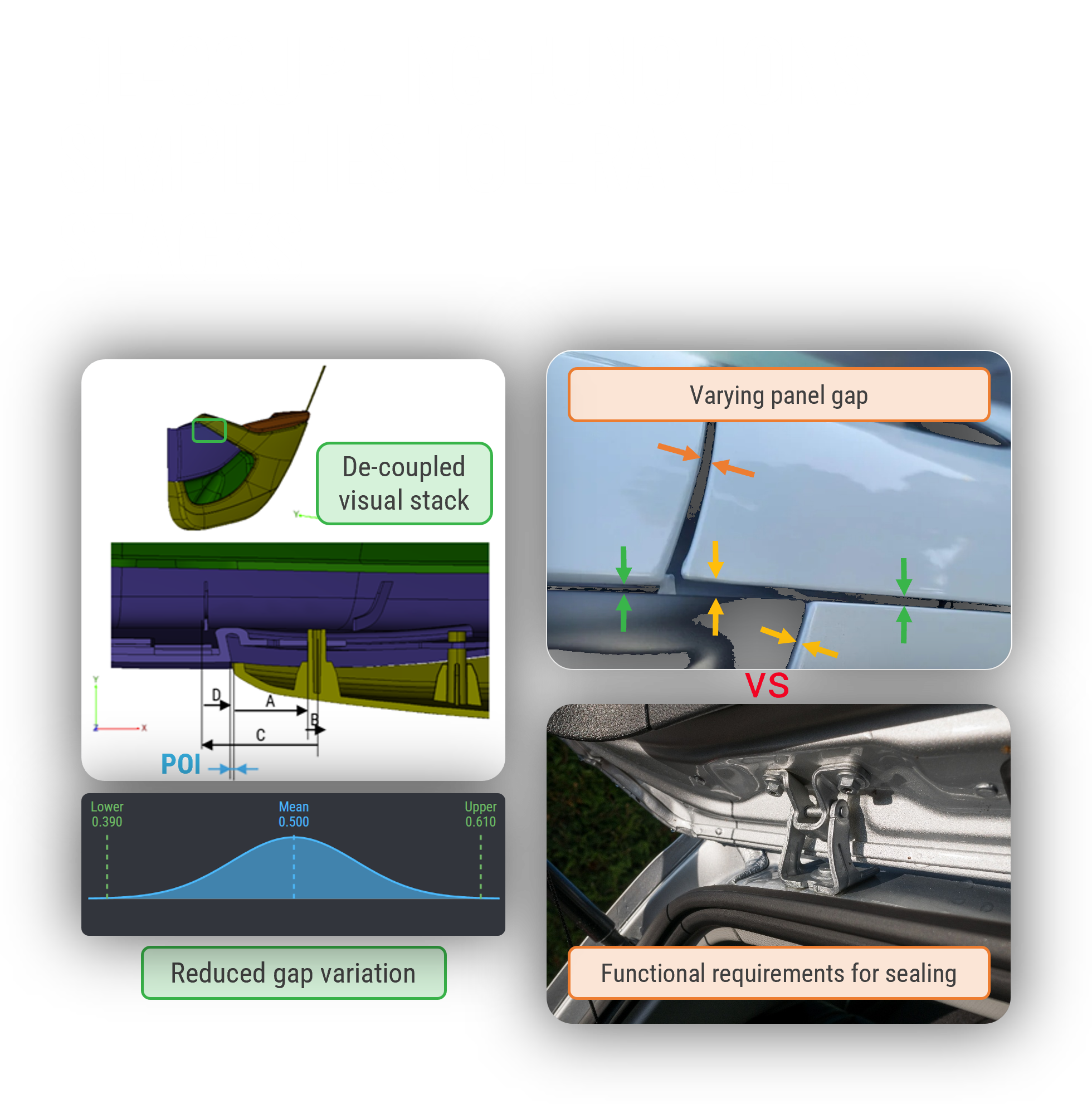
With Robust Design we aim to entangle the functionalities in a clear and de-coupled system. Ideally, each input affects only one output. Thereby we create two loops: One loop for visual alignment and a separate loop for functional alignment. And each loop gets its own independent tolerance stack. So, once your requirements change, you know exactly which interfaces are affected and which parameters to tune. Understanding which interfaces are affected has become a lot easier with our RD8 path finder and the interface detection.
However, even when you separate your visual and functional requirements into different loops, the complexity within your functional loop will reduce product quality and performance.
As an example, controlling critical alignments through long tolerance stacks in brackets and clamps is a bad idea. Again, in CAD everything sits perfectly nominal and has sufficient clearance. In reality, variation multiplies with every single mating surface and dimension.
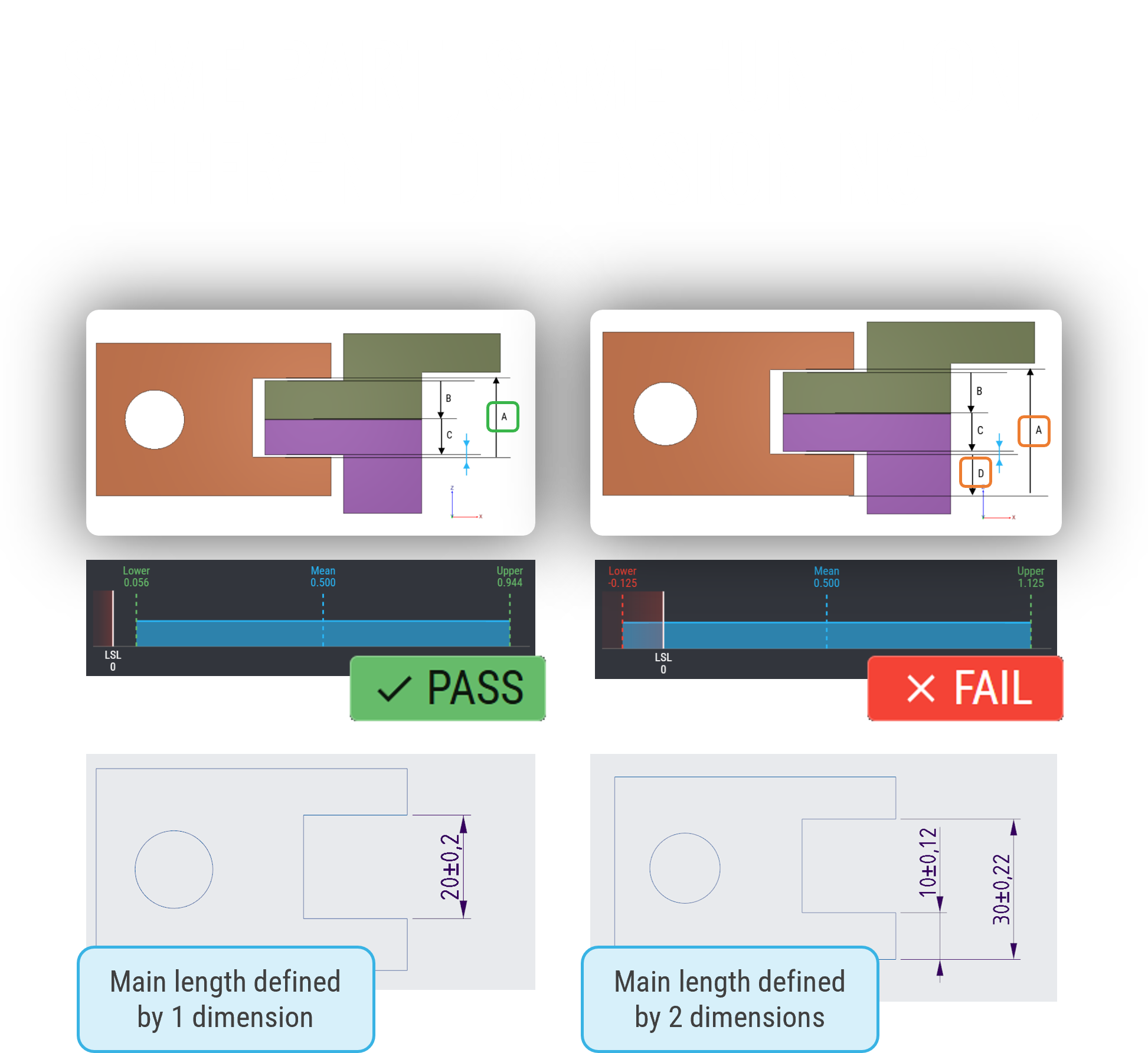
As the images show: Same part, same function, only the dimensioning is different.
When you rely on too many dimensions or too many parts are involved to deliver a single function, stack-ups quickly exceed allowable functional limits. For low volume production you could account for this with manual changes in assembly. But for high volume, you need to tighten tolerances and chase impossible precision targets.
By linking your functional requirement to shorter tolerance stacks, you win. As the image above shows, changing a single dimension makes the difference between a "FAIL" and a "PASS".
When you reduce the stack, individual tolerances can become wider, leading to cheaper manufacturing. Product quality suddenly relies on smart architecture, not expensive precision machining.
So far, we only looked at improving tolerance stacks. Now, if we take a step back and check how many tolerance stacks you are doing, the larger the amount, the more likely your core issue lies in overconstraints.
How do you know if a tolerance stack is actually verifying a functional requirement, or if it only exists because your system is overconstrained? That's where the understanding of kinematics comes into the picture.
When you have an overconstraint, your CAD is only telling you part of the truth. Across many automotive and complex hardware projects that we have been involved in at RD8, we see a recurring pattern: Teams trust what the CAD assembly shows, and then reality tells a very different story after the parts are produced. Typical issues that we observe once you get the manufactured parts:
- Assembly forces are much higher than predicted
- Unpredictable deformations prevent full functionality
- Rattle and inconsistent performance that appears only in testing
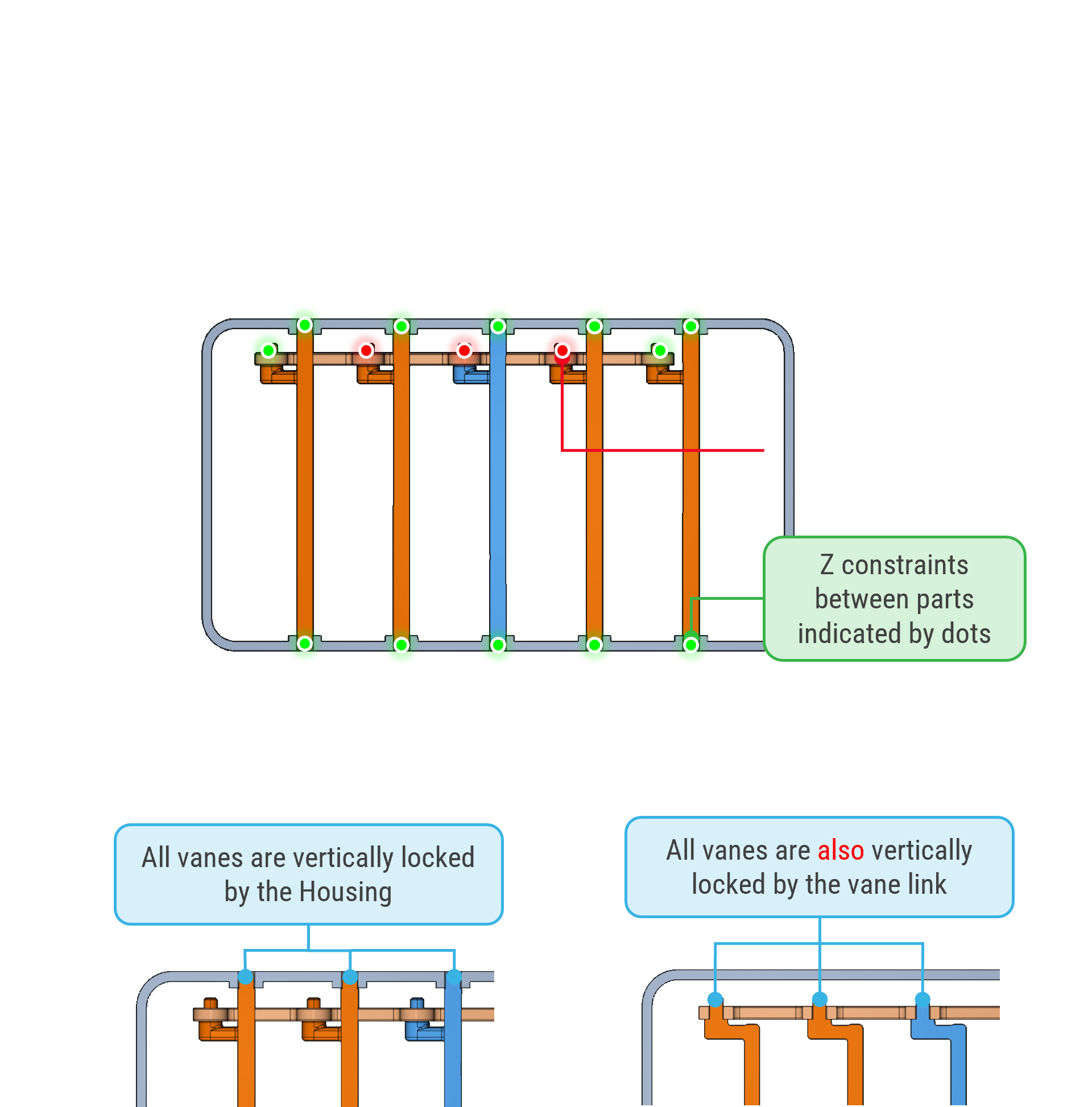
In most cases, the root cause is overconstraints. Even when your CAD fits, if your product has overconstraints, manufacturing variation will lead to stresses and friction. What is happening is that multiple parts are all trying to control the same degrees of freedom, which the CAD would actually show, if you know where to look.
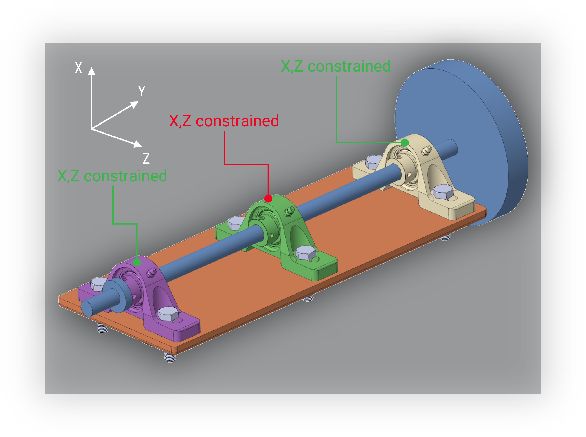
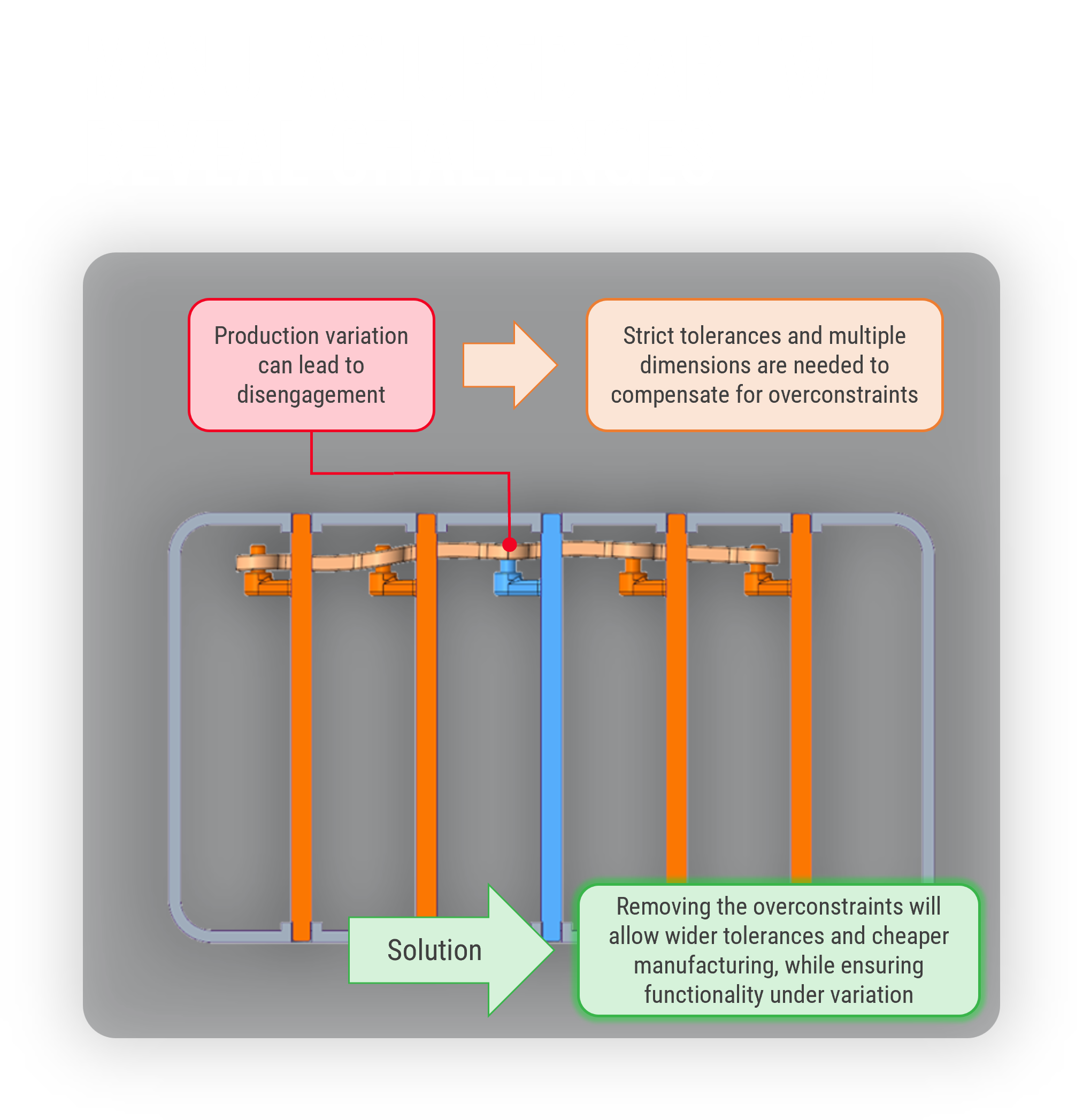
Let us look at a simple example: an axle supported by three bearings instead of two. A rotating axle can be found in any industry, from drive shafts in automotive hardware to cylinders sliding inside cylinders in medical devices.
The main question from a kinematic perspective is, if you have two clearly defined bearings, or more than that.

When you add that third bearing, you create an overconstrained system. To make the parts assemble and function without overload or friction, you are forced to:
- Tighten the positional tolerances on all three bearing mounts
- Calculate complex, interdependent tolerance stacks just to ensure it aligns
- Drive up machining and inspection costs significantly
Again, just because it all fits and aligns in CAD, doesn't mean the real parts are the same.
When you apply Robust Design principles, you drastically reduce the number of tolerance stacks you need to calculate. It highlights which tolerance stacks can be completely eliminated simply by increasing clearance and removing a redundant constraint(=contact), without changing the product's function.
The critical difference when applying Robust Design is that we define the kinematics for each interface early to reduce complexity instead of adding it: Drawings require fewer specifications, with clear intention behind each tolerance, and assemblies behave consistently across variation. That means that the product can be launched on time without requiring multiple unplanned rounds of rework.
With more complex products it gets harder to identify the overconstraints, and harder to solve the related issues. The RD8 Software supports you making the tolerance stacks and lets you know if your system is overconstrained. It highlights overconstraints right from the concept stage, so engineers can see, discuss, and align on the ideal part interfaces, long before the first parts arrive and expensive tests reveal the issue.