RD8 Snap Hook Calculator
Free tool for Robust Design Snap Hooks calculations - to handle variation and ensure self-locking.
How to use the calculator
The calculator is intetend for quick look-ups and rough estimates. For more details see RD8.Software.
Main features of the free app:
- Tolerance Lookup
- Process Guidance
- Stack and clearance estimates
How to use
- A) Input the number of parts in the stack
- B) Input the characteristic length of the parts
- C) Choose tolerance standard and grade
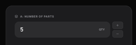
A) NUMBER OF PARTS
Input the estimated number of parts in the given stack.
See the supporting illustrations.
You can tweak the analysis for more complex assumptions is needed. In example most stacks will feature a locating feature and then a position tolerance to the next part. A rough estimate is to double up and multiply by 2.
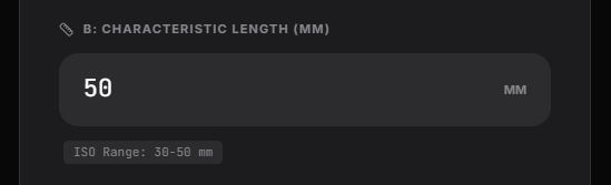
B) characteristic length
The characterist length is an estimate for the average size of the parts in the assembly. The purpose is to figure out which domain you are in. If you are designing a wind turbine or an earpiece.
In example:
- Part 1: 50 mm
- Part 2: 10 mm
- Part 3: 40 mm
The characteristic lenght would be:
(50 mm + 10 mm + 40 mm)/3 = approx. 33 mm.
Even though the assumptions are rough - you would often be surpiced about the accuracy. Making a qualified estimate in the start of a project is worth a lot instead of neglecting it.
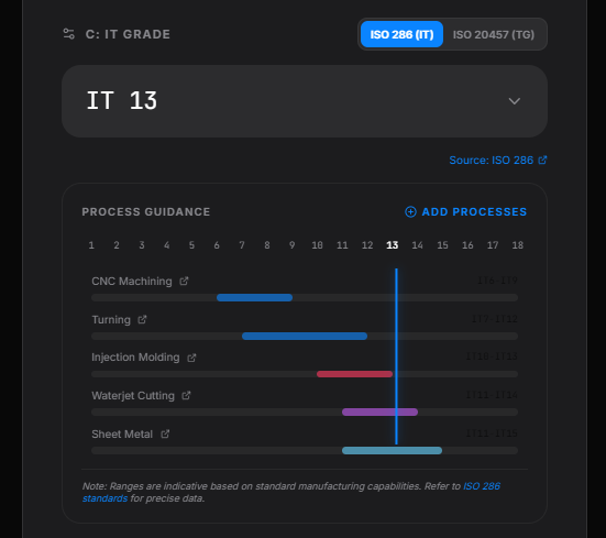
C) Choose tolerance standard
Toggle between
- ISO 286 (IT Grades)
- ISO 20457 (TG Grades)
The IT Grades standard let you choose a set of different production processes. See the chart for the capabilities.
The TG standard is specifically suited for plastic injection molded parts. You need to provide additional information about if the dimensions are toolbound or non-toolbound.
Toolbound
The geometry of the molded part is defined in the same tool half.
Non-toolbound
The geometry of the moulded part is defined across tool halfes.
How to read the charts
A lower value represents a more fine tolerance.
A higher value represents a more coarse tolerance.
If you choose higher values for the given process - often parts will be easier to source, manufacuture, keep in control.
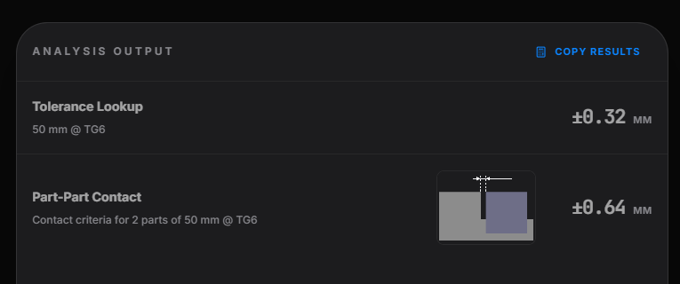
The output
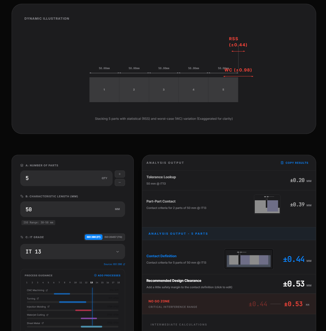
Tolerance Lookup - shows the dimension at the given standard.
The Part-Part Contact multiplies the result by 2 to estimate the needed clearance between two parts (at worst case).
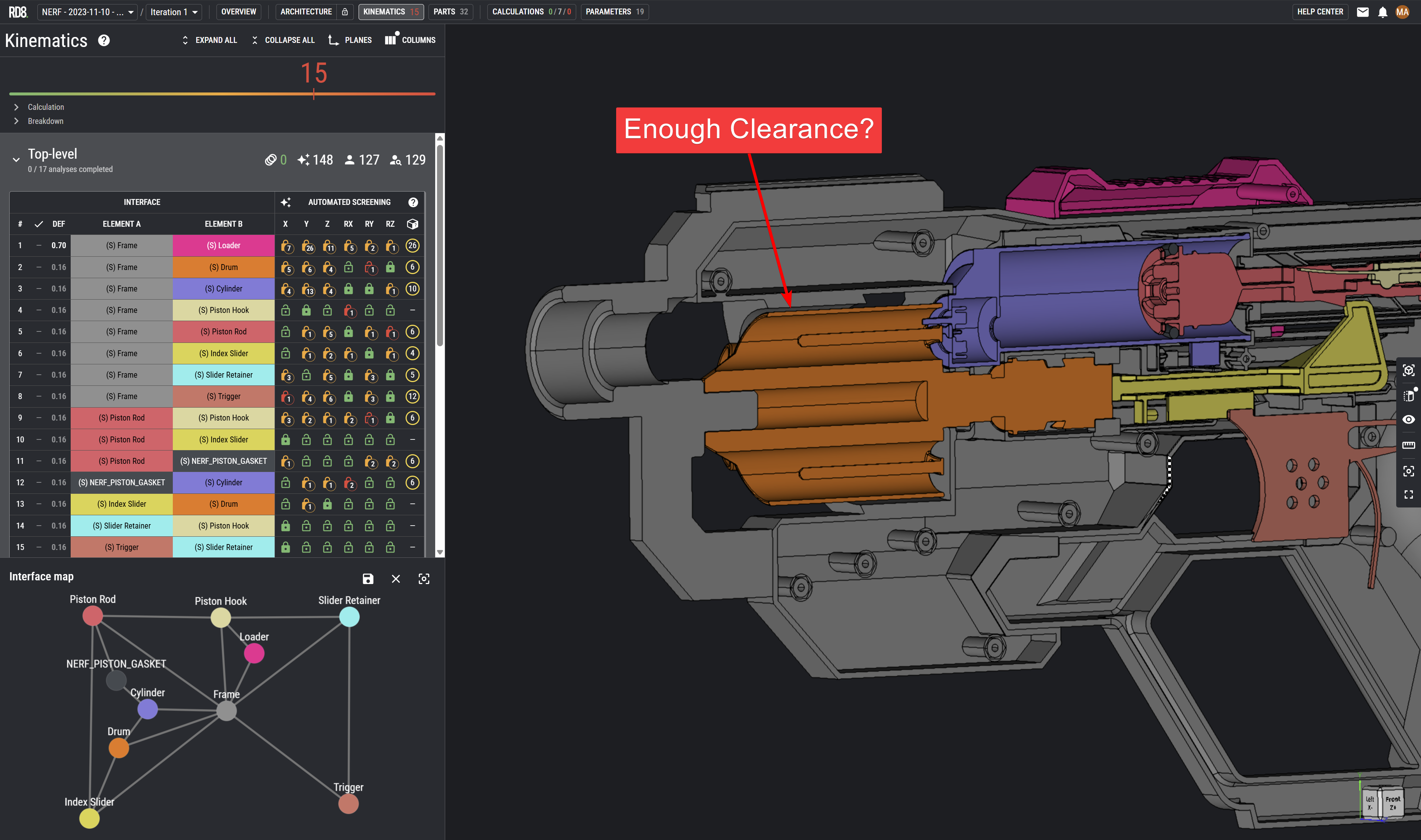
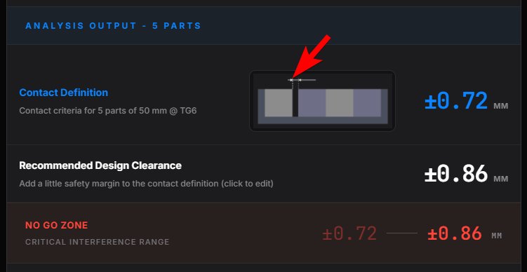
Analysis Output
This section displays the estimated clearance in a design en order to ensure if there is clearance or potential contact between the parts. This value is used as the "Contact Definition" input in the RD8 Software.
If clearance is wanted - then you should add a little bit extra clearance. As a standard +10% is added.
Click the value to modify.
It is recommended to choose and decide on a global 'Design Clearance' that all designers in the project use and can relate to everytime they need to add clearance in the CAD model.
In this example - it would make sense to modify the "Recommended Design Clearance" to +/- 0.90 mm - a number that is easy to remember for the design team.
The "No Go Zone" is in the space just in between the choosen design clearance and the contact definition. It is recommended not to leave any clearance is this threshold.
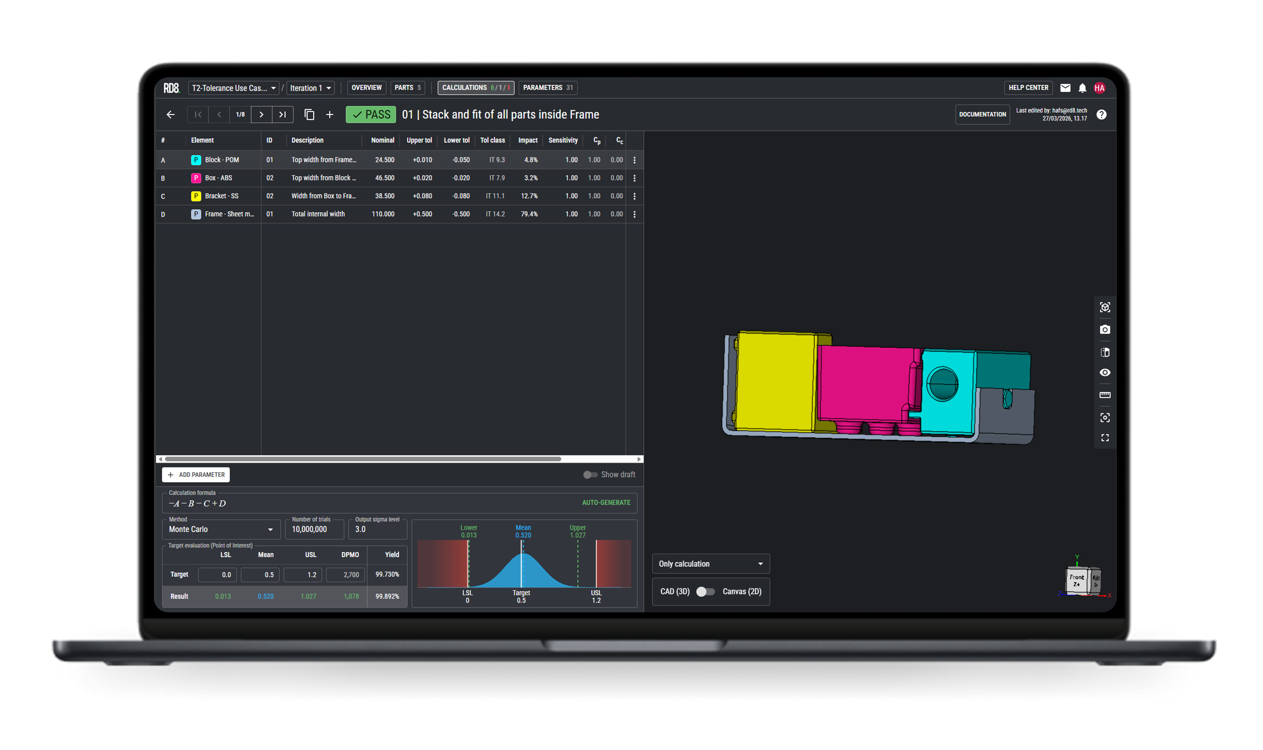
Master tolerances with RD8 software
For more detailed analysis check the RD8.Software application.
RD8.Software is integrated with the a CAD file, tolerance lookups, can do Monte Carlo simulations, check your constraint assumptions and much more.
Get in touch with our experts
Ready to bring structure and predictability to your tolerance work?
Shoot us a message and we will get back as soon as possible.


By submitting, you accept RD8's Privacy Policy and Terms of Service.