Background
I see this over and over again. Teams are having a hard time to define a threshold for their CAD models - a 'Design Clearance' - as a general guideline for a team to build sufficient clearance where needed - in order to ensure clear and reliable contact surfaces as intended.
RD8 Software - Mastering interfaces DURING development of CAD
RD8 Software is the king of interface analysis and can x-ray and evaluate constraints between parts in seconds to give instant feedback for clarity and potential improvements.
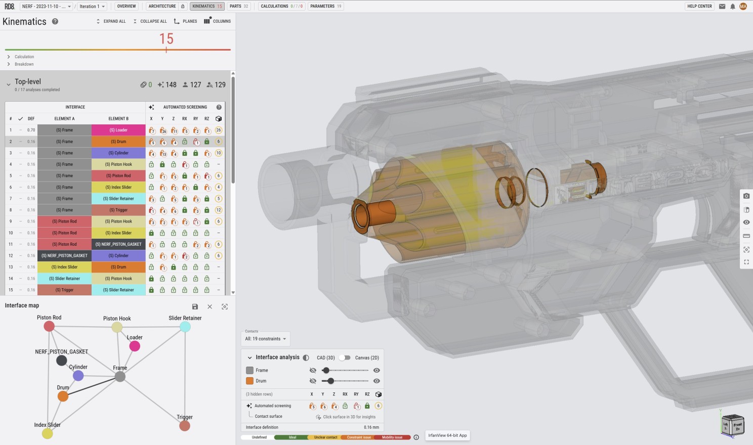
More about the software here.
Lite Tools - Making initial estimates BEFORE going into CAD
Making initial estimates for clearances - before you start to build your CAD model - is crucial for mastering the robustness of a design.
My advice is to define 3 numbers to be shared in the design team.
- A contact definition - when can you assume contact between mating surfaces
- A 'NO GO Zone' - a clearance interval to avoid - where there is a chance for contact and clearance - depending on the variation scenario.
- A design clearance definition - a clear (round) number that everyone in the team can remember and uses as default during modelling to ensure sufficient clearance to guarantee a clear contact scheme between parts.
In order to establish a qualified set of definitions you need to consider a few project aspects:
- What size are you working within? A wind turbine or a hearing aid?
- How many parts do you have in your assembly - and what is typical stack/chain-length?
- What manufacturing processes and capabilities do you intent to use?
In order to make an initial estimate - the process is quite simple.
- Estimate how many parameter/parts that is in your product/module.
- Estimate a characteristic length - the average size of a part.
- Estimate the the tolerance for the characteristic length at a given process.
- Do a stack-up analysis for expected tolerance variation for the given process with the number of parameters/parts.
This lite tool will do these calculations for you and define the 3 important numbers that you can base you CAD development on:
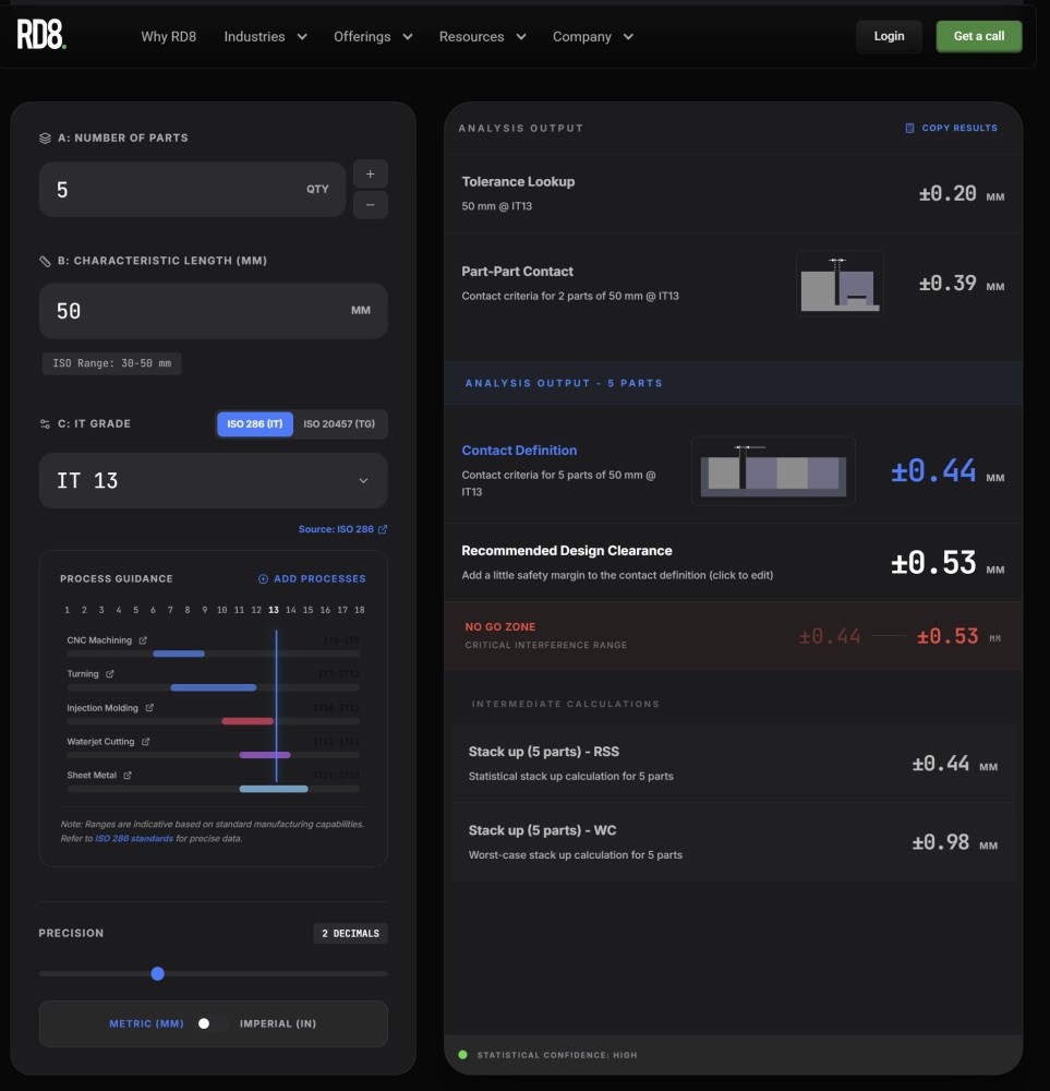
Try the free tool here.
The tool can lookup IT- and TG-grades and make the rough estimates for you in seconds.
The tool is only intended for rough estimates - for more detailed and nuanced estimates use the full RD8 Software.
Add your comments on LinkedIn: https://www.linkedin.com/pulse/mastering-clearances-mechanical-designs-markus-kyr%C3%B8-t5y4e/