1D Tolerance Stack-Up Cheat Sheet.
Download the RD8 1D Tolerance Stack-up Cheat Sheet
Your go to guide for everything related to Tolerance stack up analysis.
Fill out the form below, and the cheat sheet will be sent to your email.
By submitting, you accept RD8's Privacy Policy and Terms of Service.
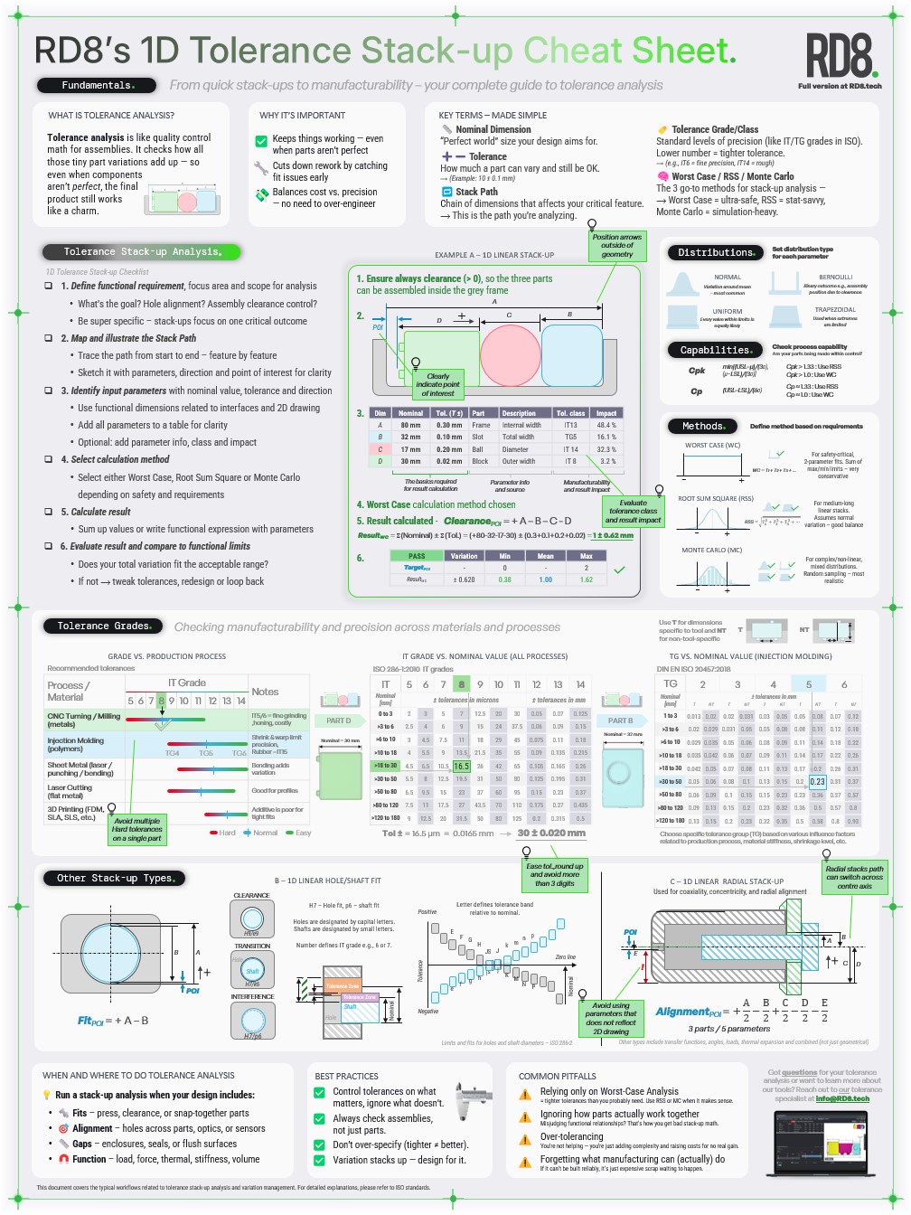
1D Tolerance Stack-Up Cheat Sheet.
Tolerance analysis is like quality control math for assemblies. It checks how all those tiny part variations add up - so even when components aren't perfect, the final product still works like a charm.
Good tolerance analysis ensures that:
Master tolerances with RD8 software
Instead of relying on gut feeling or Excel-based stack-ups, RD8 gives your team a modern, visual, and collaborative piece of software to manage variation. Whether you're designing precision mechanisms or high-volume components, we help you brings clarity to complex assemblies - and avoid costly rework, ensure functionality, and speed up development cycles.

Key Terms - Made Simple
Nominal Dimension
Tolerance
Stack Path
→ This is the path you're analyzing.
Tolerance Grade/Class
Lower number equals a tighter tolerance.
Worst Case /RSS /Monte Carlo
• Worst case = ultra-safe,
• RSS = stat-savvy,
• Monte Carlo = simulation-heavy
Tolerance Stack-up Analysis
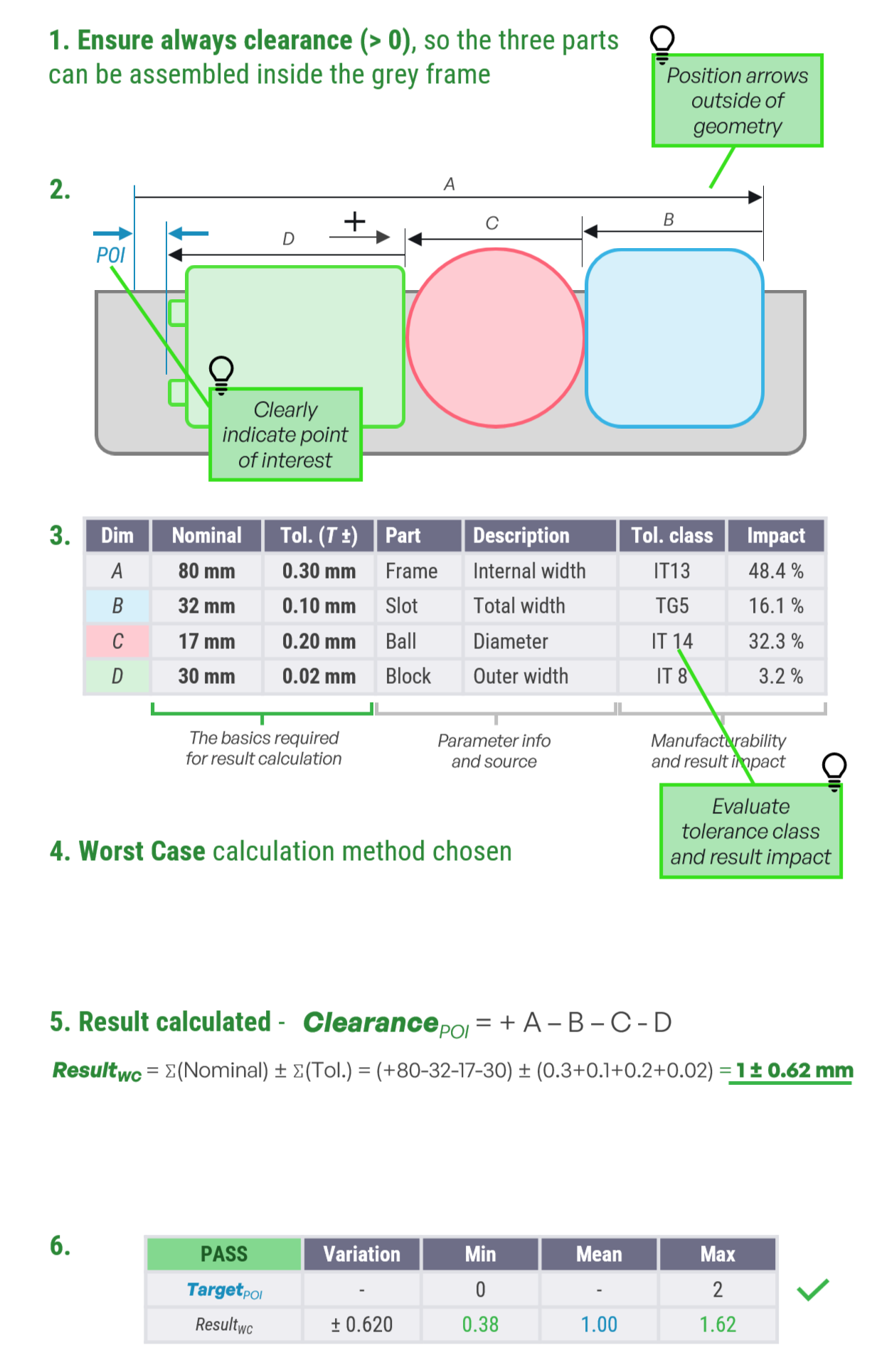
1. Define functional requirement, focus area and scope for analysis
• What's the goal? Hole alignment? Assembly clearance control?
• Be super specific - stack-ups focus on one critical outcome
2. Map and illustrate the Stack Path
• Trace the path from start to end - feature by feature
• Sketch it with parameters, direction and point of interest for clarity
3. Identify input parameters with nominal value, tolerance and direction
• Use functional dimensions related to interfaces and 2D drawing
• Add all parameters to a table for clarity
• Optional: add parameter info, class and impact
4. Select calculation method
• Select either Worst Case, Root Sum Square or Monte Carlo depending on safety and requirements
5. Calculate result
• Sum up values or write functional expression with parameters
6. Evaluate result and compare to functional limits
• Does your total variation fit the acceptable range?
• If not → tweak tolerances, redesign or loop back
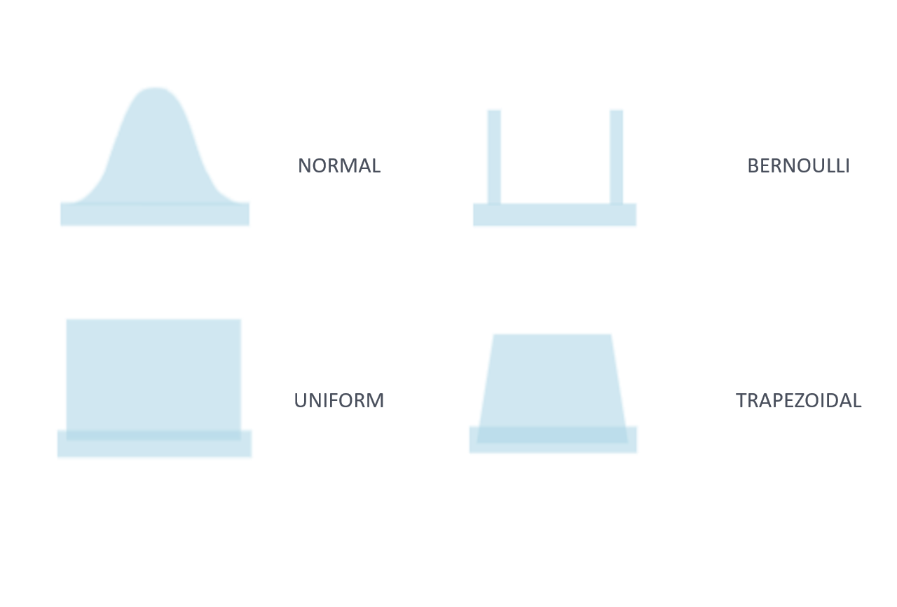
Distributions
Set distribution type for each parameter
• Normal - Variation around mean, most common
• Bernoulli - Binary outcome e.g. assembly position due to clearance
• Uniform - Every value within limits is equally likely
• Trapezoidal - Used when extremes are limited
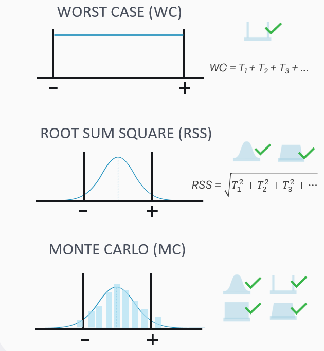
Methods and Capabilities
Define method based on requirements
• Worst Case - For safety-critical, 2-parameter fits. Sum of max/min limits - very conservative
• Root Sum Square - For medium-long linear stacks. Assumes normal variation - good balance
• Monte Carlo - For complex/non-linear, mixed distributions. Random sampling - most realistic
Check process capability
Are your parts being made within control?
• Cpk = min[(USL-μ)/(3σ) , (μ-LSL)/(3σ)]
- Cpk > 1.33 : Use RSS
- Cpk > 1.00 : Use WC
• Cp = (USL - LSL)/(6σ)
- Cp ≈ 1.33 : Use RSS
- Cp ≈ 1.00 : Use WC
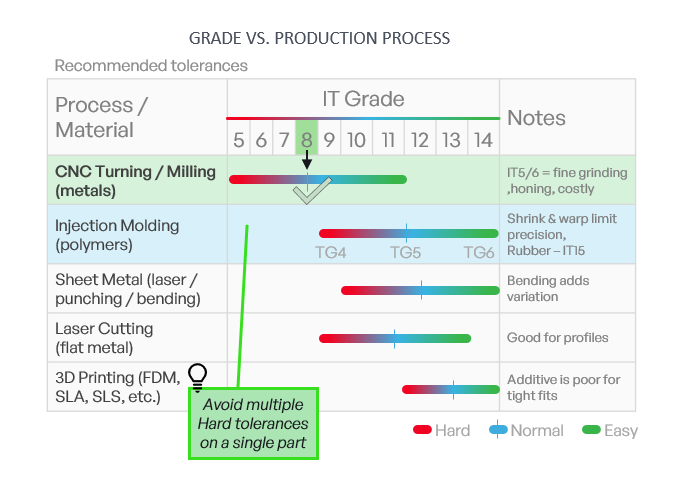
Tolerance Capabilities by process
• Shows which tolerance grades different manufacturing processes can realistically achieve
• CNC machining provides the tightest tolerances
• Injection molding, sheet-metal processing, laser cutting, and especially 3D printing offer progressively looser accuracy
• The color-coding indicates what is easy, normal or difficult for each process
• Emphasizes the importance of choosing tolerances that match the process capability
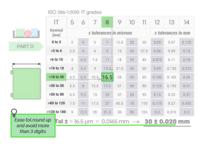
IT grade tolerances for a 30 mm Dimension
• Shows how ISO 286 IT grades correspond to actual numerical tolerances
• For a nominal size of 30 mm, IT8 gives tolerance of 16.5μm
• This converts to approximately 0.0165 mm, rounded to 0.20 mm for ease of use
• Table highlights how tolerances increase with both IT grade and part size
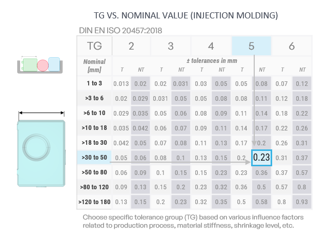
Injection Molding Tolerance Group (TG) for a 32 mm Dimension
• Shows how DIN EN ISO 20457 tolerance groups define achievable accuracy in injection-molded parts
• For a nominal size of 32 mm, TG5 corresponds to a tolerance of about 0.23 mm
• Table illustrates how tolerances vary with both part size and chosen TG level
• Highlights the impact of material behavior, shrinkage, and process variation on achievable precision
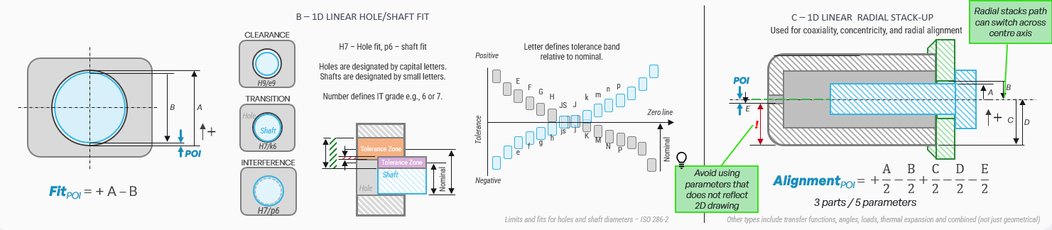
Other Stack-Up Types
Tips and tricks
Run a stack-up analysis when your design includes:
Alignment - holes across parts, optics, or sensors
Gaps - enclosures, seals, or flush surfaces
Function - load, force, thermal, stiffness, volume
Best practices
Always check assemblies, not just parts.
Don't over-specify (tighter ≠ better)
Variation stacks up- design for it
Common pitfalls
= tighter tolerances than you probably need. Use RSS or MC when it makes sense.
Ignoring how parts actually work together
Misjudging functional relationships? That's how you get bad stack-up math
Over-tolerancing
You're not helping - you're just adding complexity and raising costs for no real gain
Forgetting what manufacturing can (actually) do
If it can't be built reliably, it's just expensive scrap waiting to happen.
Get in touch with our experts
Our outside-in approach brings new perspectives to traditional designs and typically results in radically new ideas. Get in contact with a RD8 Robust Design specialist to hear how we help you – either by our consulting or tolerance analysis software.
Shoot us a message and we will get back as soon as possible.


By submitting, you accept RD8's Privacy Policy and Terms of Service.